What is a Breadboard?
A breadboard is a tool used to build and test simple electronic circuits without needing to glue or solder anything.
Think about toy building bricks.
When you snap two bricks together, they stay connected and work as one piece.On a breadboard, when you push a wire or a component into a hole:
Inside, tiny metal clips “grab” it.
Those clips are already connected to other holes.
So it’s like the pieces are snapping together inside the board.
Why Use a Breadboard?
A breadboard is used to test circuits because:
No Permanent setup. You can plug in components and remove them once testing is done.
Allows expermentation. You can easily change things if something doesn’t work
reat for learning and experimenting. You can create as many projects as possible.
Types of Breadboards
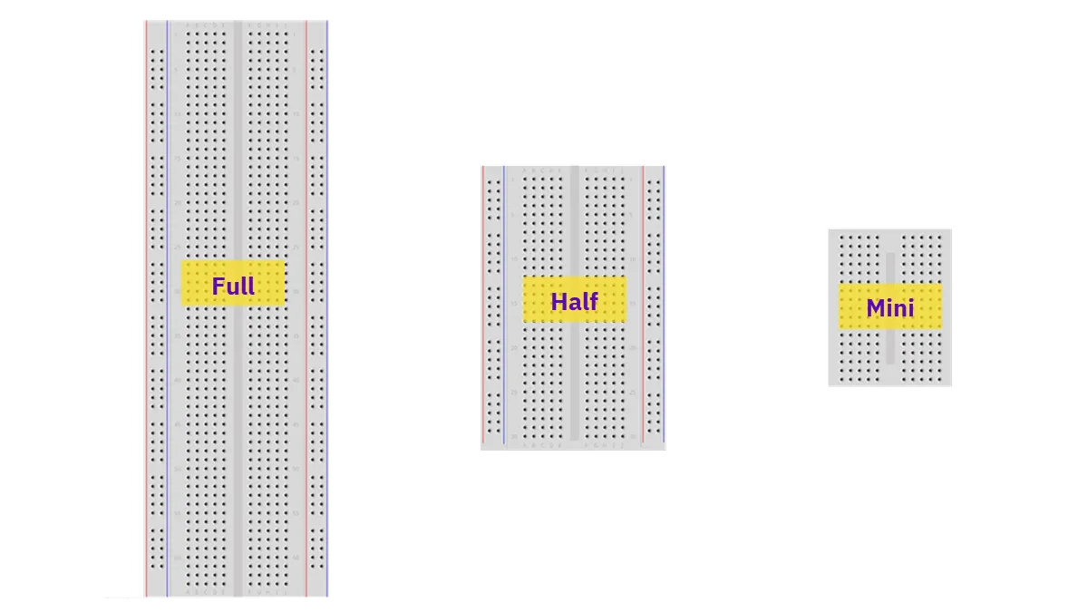
Breadboards come in different types, depending on how and where you want to use them. There are three types:
- 1
Full Size: This is the biggest type, usually with about 830 holes and is around 165 mm × 55 mm.
- 2
Half Size: This is medium-sized, with about 400 holes and is roughly 83 mm × 55 mm.
- 3
Mini Size:This is the smallest type, usually with about 170 holes and is around 45 mm × 35 mm.
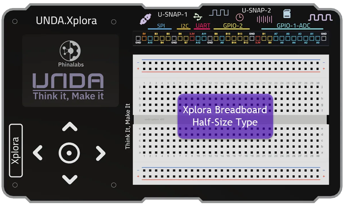
UNDA.Xplora Kit makes use of the Half Size Breadboard.
Parts of A Breadboard
A breadboard is usually in rectangular size full of tiny holes and these holes are not just placed randomly - they are connected in a special way. These connection make it easy to build circuits on the breadboard.
A breadboard is made up of the following parts:
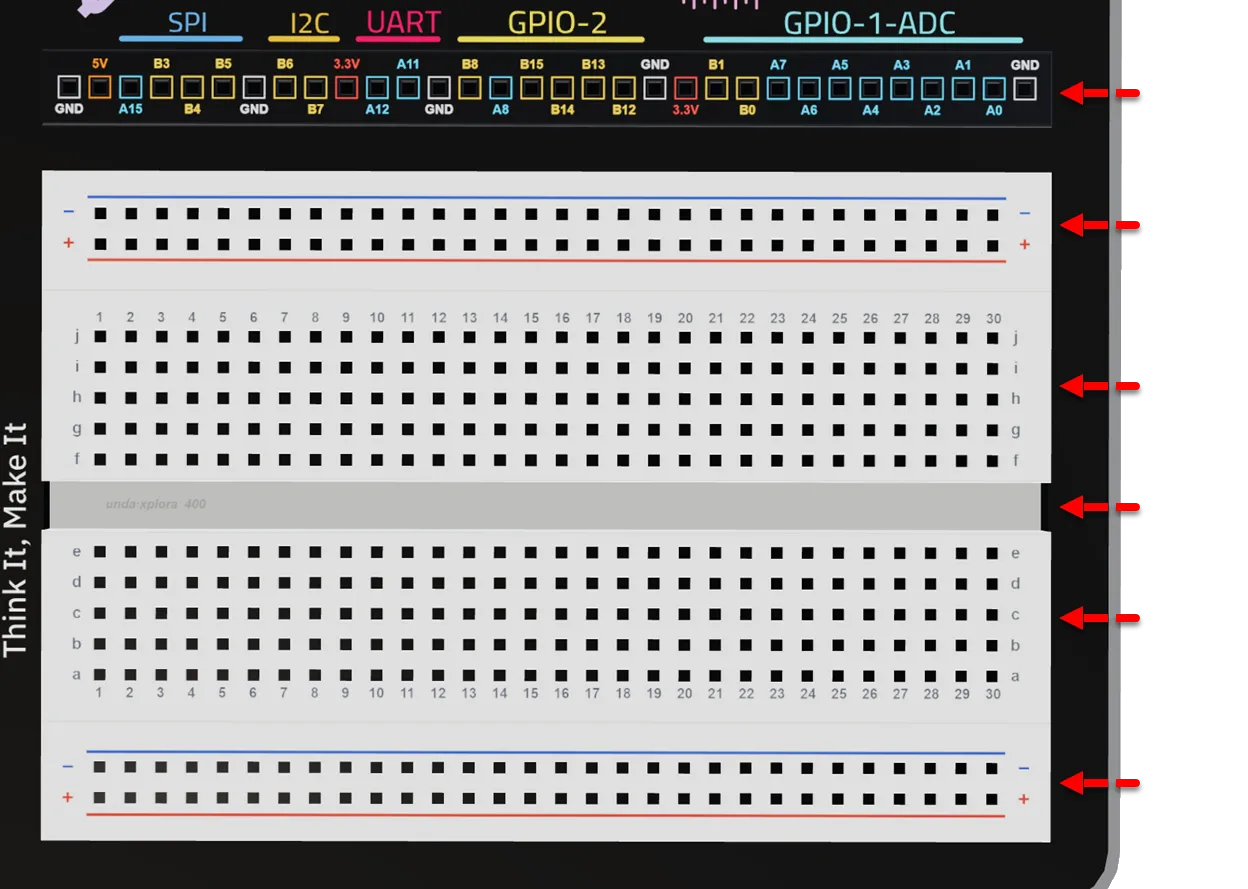
Contains various pins such as digital, power pins etc. used to connect to electronic components
Has both positive and negative terminal used to carry and provide power for the breadboard
The section allows users to plug in electronic components when building circuits
A slot running through the breadboard to separate the two circuit building sections of the breadboard
The section allows users to plug in electronic components when building circuits
Has both positive and negative terminal used to carry and provide power for the breadboard
Breadboard Pin Connections
The pins of the breadboard are connected in either two ways i.e terminal or bus strips.
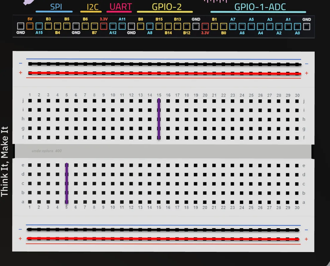
Similarly, the holes in a single row of the negative terminal of the power rail are linked together(bus strip configuration). So, if you connect GND (ground) to one hole on the negative rail, all the other holes in that row also get GND.
All the holes in a single row of the positive terminal of the power rail are linked together (bus strip configuration). So, if you connect 5V to one hole on the positive rail, all the other holes in that row also get 5V.
All the holes in a single column of the breadboard are linked together (terminal strip configuration). This means that if you insert a component or wire into one hole of a column, it is electrically connected to all the other holes in that same column.
All the holes in a single column of the breadboard are linked together (terminal strip configuration). This means that if you insert a component or wire into one hole of a column, it is electrically connected to all the other holes in that same column.
Similarly, the holes in a single row of the negative terminal of the power rail are linked together(bus strip configuration). So, if you connect GND (ground) to one hole on the negative rail, all the other holes in that row also get GND.
All the holes in a single row of the positive terminal of the power rail are linked together (bus strip configuration). So, if you connect 5V to one hole on the positive rail, all the other holes in that row also get 5V.
Therefore, the power rail section are arranged in bus strip configuration since all holes in a single row are linked together and this forms what is called horizontal continuity.
The circuit building section on the other hand is arranged in terminal strip configuration since all holes in each single column are linked together forming what is called vertical continuity.
Xplora Pinout Section
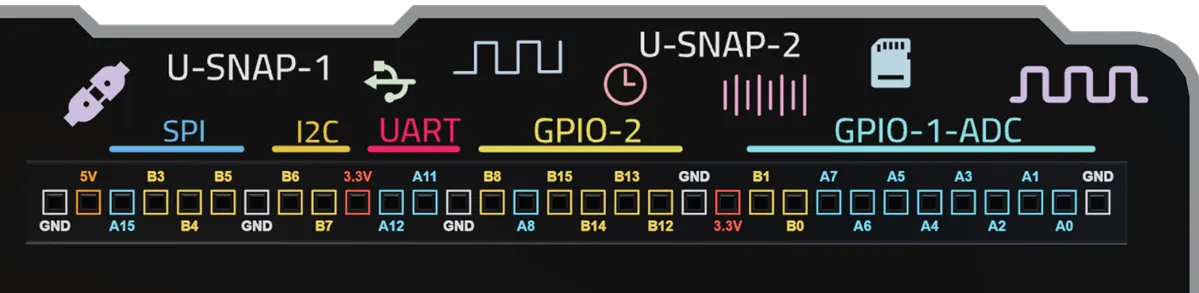
This is a Collection of 32 ports; Power, GPIO, ADC, PWM and Communication that all serve a different purpose in building of circuits on the breadboard.
| Type | Description | Pins |
|---|---|---|
GPIO | Read digital inputs and control digital outputs. | All pins except Power and GND |
Analog (ADC) | Read analog values from sensors. | A0–A7, B0, B1 |
PWM | Control variable outputs such as LED brightness, servo position, and motor speed. | A0, A1, A2, A3, A5, A6, A7, A8, A15, B0, B1, B3, B4, B5, B6, B7, B8 |
Communication | Exchange data using SPI, I2C, or UART. | SPI: B3, B4, B5 |
Power & GND | Supply power and provide a common ground connection. | 3.3V, 5V, GND |
All UNDA.Xplora pins, except the Power (3.3V, 5V) and GND pins, can be used as GPIO pins.
Some GPIO pins also support additional functions such as ADC, PWM, SPI, I2C, or UART. This means a single pin can perform more than one function depending on your project."
Digital components work with only two states - ON or OFF - just like a light switch. This means they deal with simple signals, often called 1 or 0.
Analog components can work with a wide range of values, not just two. For example, a temperature sensor might measure 10°C, 20°C, 25°C, or 30°C.
In simple terms, digital has two states, while analog has a wide range of values in between, giving you more flexibility when building circuits.
Power Rail Section
The power rails are the long rows of holes (25 Holes) running on the edges of the breadboard usually separated from the main building area and are marked with colored stripes. Also remember, power rails have both positive terminal and negative terminal.
How to Identify Power Rails
- The positive terminal of a power rail is usually identified by a red stripe which is drawn horizontally and additionally a + sign is also placed at both ends of the terminal.
- The negative terminal of a power rail is usually identified by a blue stripe which is drawn horizontally and additionally a - sign is also placed at both ends of the terminal.
Power rails carry electricity across the board and distribute it to all parts of your circuit, making sure every component gets the electricity it needs to work.
How do we Connect Power to the Power Rails?
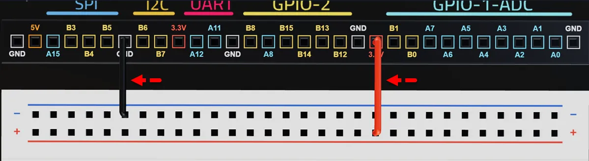
Using a jumper wire, connect one end of the wire into a 3.3V Xplora port and the other end to any of the holes of the positive(+) terminal.
With another jumper wire, connect one end of the wire into any GND Xplora port and the other end to any of the holes of the negative(-) terminal.
Circuit Building Section
This section allows users to insert different components when building and testing their circuits. The breadboard has two circuit building section; top and bottom that are separated by a grove called DIP support.
Each section has 150 pins i.e there are 5 rows with 30 pins on each row. The circuit building section has rows and columns with each marked differently to make breadboarding easy.
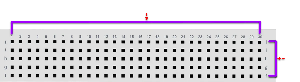
The columns run vertically and are labeled with numbers. These numbers run from 1 to 30 on both the top and bottom circuit building section.
The rows run horizontally and are labeled with letters. The bottom section is identified by letters a to e, and the top section marked by letters f to j.
Each hole in the circuit-building section of a breadboard is identified using a row–column configuration. This means every position is labeled by combining a letter (row) and a number (column). For example, hole c15 indicates a hole located in row c and column 15.
How to Insert Components on the Circuit Building Part
Find the correct row
Look at the letters on the side of the breadboard and identify the correct row e.g. row c.
Find the correct column
Look at the numbers along the top or bottom. Move along the row identified in step 1 until you reach the required column e.g. 15.
Place the component
After finding row c and column 15, you now know the exact hole called c15. Put one leg of your component (like an LED) into that hole. Place the other leg into hole c18.
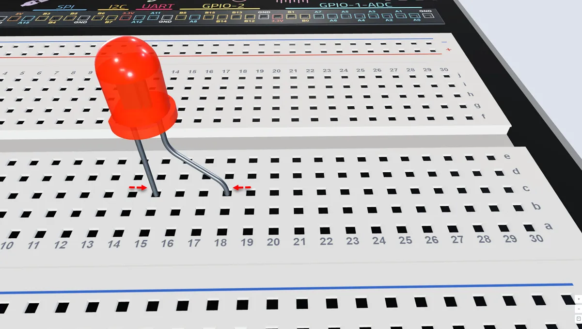
Locate the hole c15 by checking for row c and column 15 and then insert the negative leg of the LED (the shorter leg).
Locate the hole c18 by checking for row c and column 18 and then insert the positive leg of the LED (the longer leg).
Building on the Breadboard
Now it’s time to build your first circuit called Flashing Light Project.
Before building, its important to understand what a circuit is.
What is a Circuit?
A circuit is a path that lets electricity flow from a power source like a battery through wires and components like LEDs, resistors, or motors and back to the battery.
When the path is complete, the electricity powers up the components e.g. LEDs light up. If the path is broken, nothing works and no components are powered up.
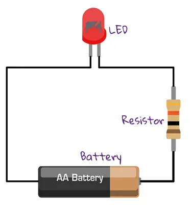
Simple LED Circuit
Based on this circuit, the wiring connections can be summarized as:
| From | Wire / Part | To | Note |
|---|---|---|---|
| Battery Positive Terminal | red | Resistor | 3.3V or 5V power |
| Resistor | red | LED Positive Leg | Resistor added to limit flow of current |
| LED Negative Leg | red | Battery Negative Terminal | This completes the path of the circuit. |
Flashing Light Project
In this project, we will create flashing light project, where an LED turns on and off repeatedly. This is called toggling.
By the end of this activity, you’ll see your LED blink and learn how simple circuits can create fun and useful effects.
For this Project, we will make use of the following components UNDA.Xplora, LED, Resistor and Jumper Wires.
Some of the basic breadboarding safety tips include:
- Check your power. Always make sure the breadboarding power of your UNDA.Xplora Kit is off before building the circuit.
- Place components carefully. Push LEDs, resistors, and wires gently to avoid bending or breaking them.
- Double-check connections. Make sure each wire and component is in the correct row/column.
- Check Polarity. Some components have polarity which means they have negative and positive terminal always ensure the correct wiring.
- Keep the area clean. Avoid using water or food when working with your circuit.
- Ask for help. If you’re not sure of anything when building your circuit, always ask your parent or guardian for help.
The following project steps are built using the simulator.
Check it out at UNDA.Xplora 3D Simulator
You can also follow the steps featuring the actual kit at:
Xplora Tutorial Page
Flashing Light Steps
To building Flashing project on UNDA.Xplora Simulator follow this steps:
Placing the LED
Drag an LED from the Components Section and place its' negative leg at breadboard hole g8 and its' positive leg at breadboard hole g11
Placing the Resistor
Drag an LED from the Components Section and place its legs at breadboard hole h11 and h15. Select the resistor and change its resistance to 220 Ohms.
Connecting to a Digital Pin
Select the Wire option (or press W on your keyboard). Connect one end of the wire to Xplora pin B15 and the other end to breadboard pin j15.
The Jumper Style box allows you to change the wire type and wire color to match your preference or make your circuit easier to read.
Connecting to the Top Negative Rail
Select the Wire option and go to jumper style and set the Jumper Type to Pre-cut and the wire color to Black. Connect one end of the wire to the GND pin and the other end to the top negative power rail.
Connecting the Negative Leg of LED to GND
Select the Wire option and go to jumper style and set the Jumper Type to Pre-cut and the wire color to Black. Connect one end of the wire to the top negative power rail and the other end to breadboard pin j8, next to the negative (–) leg of the LED.
Flashing Light Video Tutorial
Flashing Light Simulator Video Tutorial
Check out the project on the actual UNDA.Xplora kit at:
Flashing Light Project
Practice Makes Perfect
Now that you have completed your first tutorial, you can check out other projects in the simulator or with your UNDA.Xplora Kit and try to build them yourself.
There are 20 pre-done projects that you can check as you learn how to use the breadboard.
Conclusion
In this tutorial, you learned how a breadboard works, how to place and connect components correctly, how to use jumper wires, how to follow a circuit diagram, and how to check connections before powering up. With these breadboarding skills, you can continue experimenting and create bigger, more advanced circuits!
UNDA.Xplora is a fun way to learn the basics of breadboarding, electronic parts, and building your first circuit.
To build more projects and practice breadboarding use the simulator:
Check it out at: UNDA.Xplora Simulator
You can also purchase the kit and check out the tutorials for the actual kit at:
Xplora Tutorial Page