Introduction
This project introduces a simple dashboard that displays real-time input values from components like a pushbutton and a potentiometer.
A dashboard is a visual interface that shows important information in an easy-to-understand way, allowing you to quickly see what is happening in a system.
In this case, as you press the button or turn the potentiometer, the dashboard updates instantly, helping you understand how user inputs are detected and displayed.
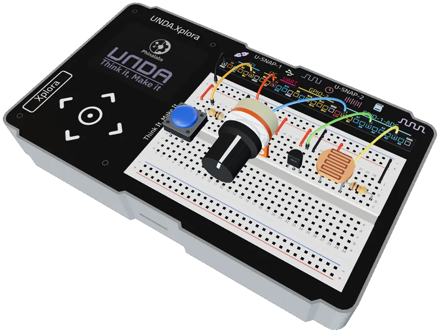
Build the Project
In this section we will explore how to build a sensor and input dashboard.
Components Used
| # | Name | Component | Qty | Description |
|---|---|---|---|---|
| 1 | LDR | 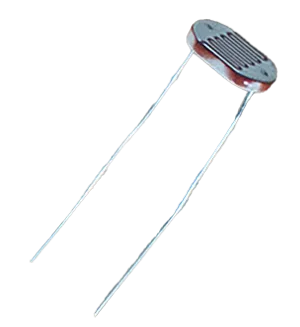 | 1 | Senses the ambient light intensity |
| 2 | Temperature Sensor | 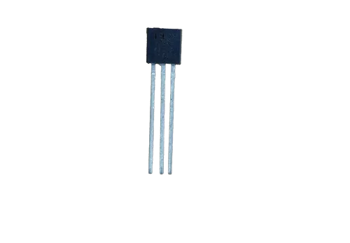 | 1 | TMP 36 with operating range between -40°C to +125°C |
| 3 | Potentiometer | 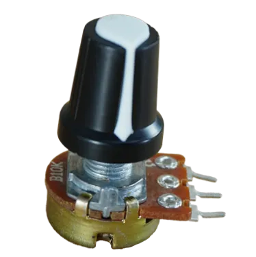 | 1 | Variable Resistance of between 0- 10 Kilo-ohms |
| 4 | Push button | 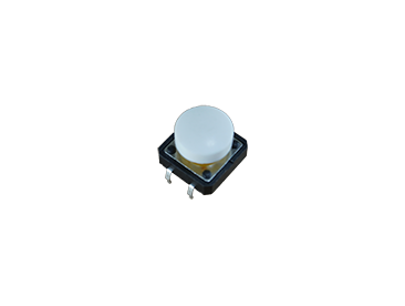 | 1 | White Colored Push button |
| 5 | Resistor | 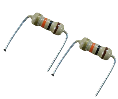 | 2 | 10 Kilo-ohm Resistor |
| 6 | Jumper Wire | 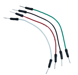 | 4 | Male-Male Jumper Wires |
| 7 | Breadboarding Jumper Wires | 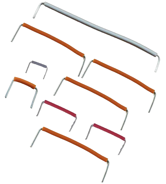 | 9 | Choose the best-sized breadboarding wire |
| 8 | Battery Connector | 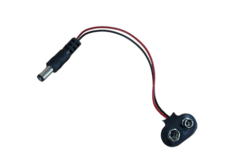 | 1 | 9V Battery Connector |
| 9 | Battery | 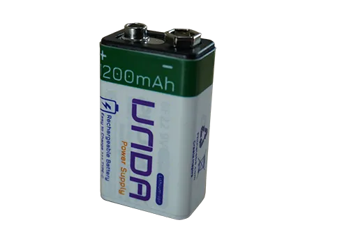 | 1 | UNDA 9V Rechargeable Battery |
| 10 | UNDA:Xplora | 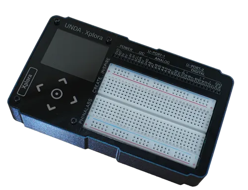 | 1 | Xplora Electronics Kit |
Step 1
Connecting the components on the breadboard
| From | Wire / Part | To | Note |
|---|---|---|---|
| Pushbutton | Push button | Breadboard Pins (bottom-d1 & d3)(top-g1 & g3) | Connecting Pushbutton on the Breadboard |
| Potentiometer | Potentiometer | Breadboard Pins f10, f12 & f14 | Connecting Potentiometer on the Breadboard |
| Temperature Sensor | Temperature Sensor | Breadboard Pins f18, f19 & f20 | Connecting Temperature Sensor on the Breadboard |
| Light Sensor | Light Sensor | Breadboard Pins f23 & f26 | Connecting Light Sensor on the Breadboard |
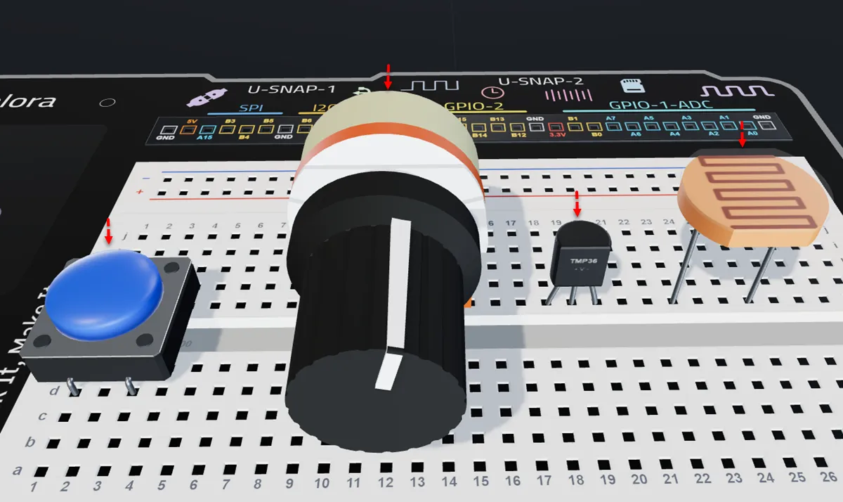
Insert the pushbutton with its bottom pins in breadboard pins d1 and d3, and its top pins in g1 and g3.
Place the potentiometer into the breadboard with Pin 1 in f10, Pin 2 in f12 (signal pin), and Pin 3 in f14.
Place the TMP36 with the flat side facing you and insert Pin 1 (+) in f18, Pin 2 (Signal) in f19, and Pin 3 in f20.
Insert the light sensor with one leg in breadboard pin f23 and the other in pin f26.
Step 2
Connecting the resistors for the light sensor and push button
| From | Wire / Part | To | Note |
|---|---|---|---|
| Breadboard Pin g3 | Resistor 10 Kilo-ohm | Breadboard Pin g7 | Pull-down resistor for the Push Button |
| Breadboard Pin g26 | Resistor 10 Kilo-ohm | Breadboard Pin g30 | Forms a Voltage-divider resistor with the Light Sensor |
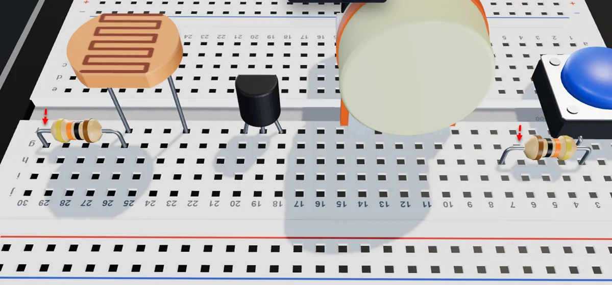
Insert a 10 kΩ resistor with one leg in breadboard pin g3 and the other in breadboard pin g7.
Insert a 10 kΩ resistor with one leg in breadboard pin g26 and the other in breadboard pin g30.
Step 3
Connecting the components to (power 3.3V)
| From | Wire / Part | To | Note |
|---|---|---|---|
| Xplora 3.3V Pin | red | Top Positive Breadboard Rail | Connecting 3.3V to top positive power rail |
| Top Positive Breadboard Rail | red | Breadboard Pin j1 | Supplies 3.3V to the push button |
| Top Positive Breadboard Rail | orange | Breadboard Pin j14 | Supplies 3.3V to the potentiometer |
| Top Positive Breadboard Rail | orange | Breadboard Pin j18 | Supplies 3.3V to the temperature sensor |
| Top Positive Breadboard Rail | orange | Breadboard Pin j23 | Supplies 3.3V to the light sensor |
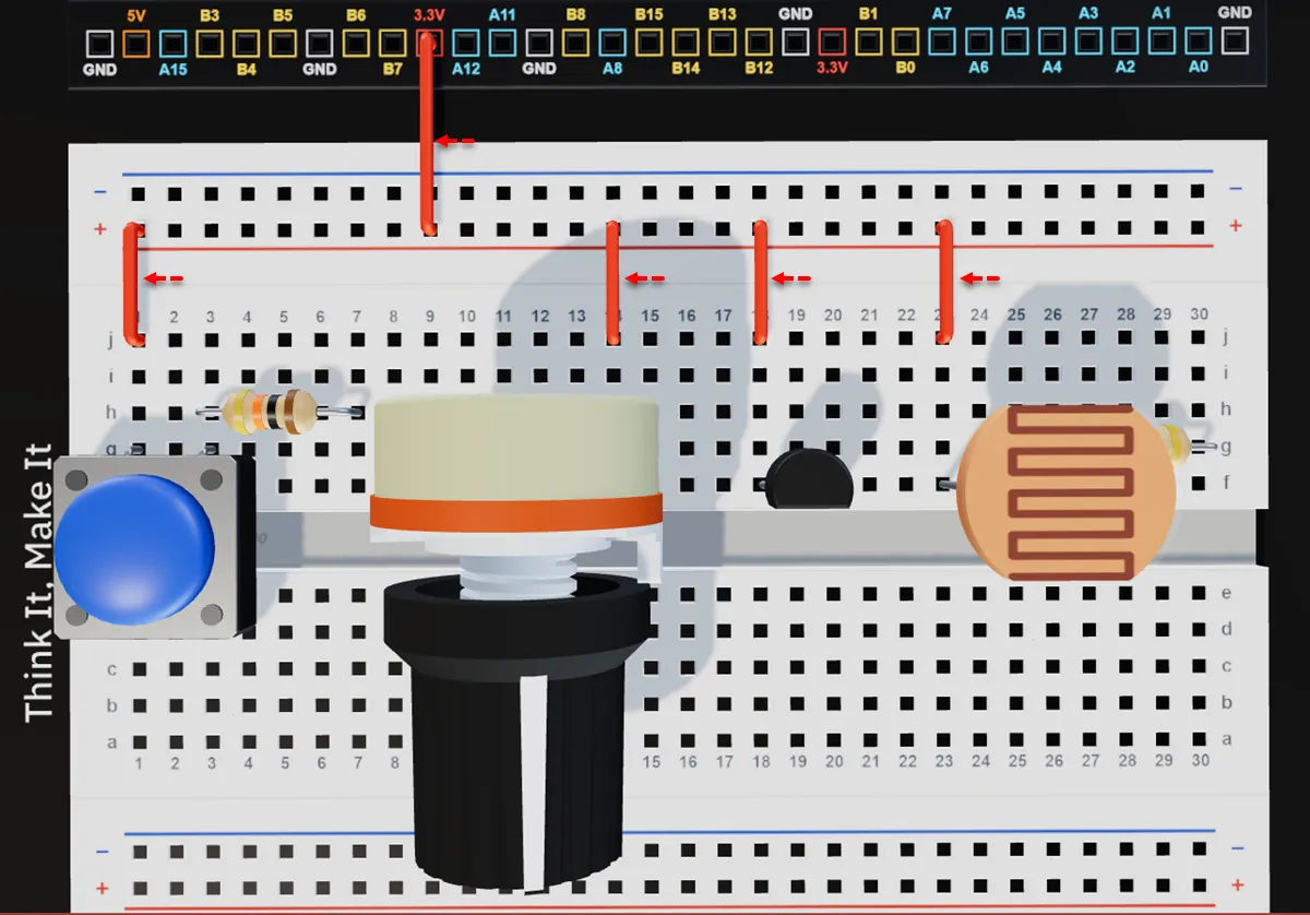
Connect a breadboarding jumper wire from the 3.3V pin on your kit to the top positive breadboard rail.
Connect a breadboarding jumper wire from the top positive breadboard rail to breadboard pin j1.
Connect a breadboarding jumper wire from the top negative breadboard rail to breadboard pin j14.
Connect a breadboarding jumper wire from the top positive breadboard rail to breadboard pin j18, next to the positive pin of the TMP36 sensor.
Connect a breadboarding jumper wire from the top positive breadboard rail to breadboard pin j23, next to the pin 1 of the LDR.
Step 4
Connecting the components to Ground
| From | Wire / Part | To | Note |
|---|---|---|---|
| Xplora GND Pin | black | Top Negative Breadboard Rail | Connects Bottom Negative Breadboard Rail to GND |
| Top Negative Breadboard Rail | red | Breadboard Pin j7 | Connects Push Button to GND |
| Top Negative Breadboard Rail | gray | Breadboard Pin j10 | Connects Potentiometer to GND |
| Top Negative Breadboard Rail | gray | Breadboard Pin j20 | Connects Temperature Sensor to GND |
| Top Negative Breadboard Rail | gray | Breadboard Pin j30 | Connects Light Sensor to GND |
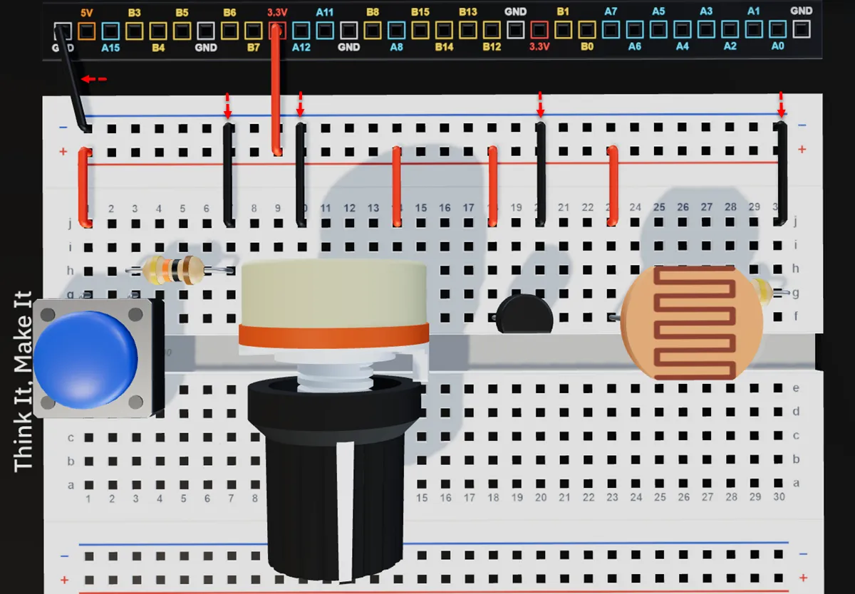
Connect a jumper wire from any GND pin on your kit to any pin of the Top negative breadboard rail.
Insert a breadboarding jumper wire from the top negative breadboard rail to breadboard pin j7.
Run a breadboarding jumper wire from the top negative breadboard rail to breadboard pin j10.
Run a breadboarding jumper wire from the Top negative breadboard rail to breadboard pin j20, (next to the negative pin of the tmp36).
Run a breadboarding jumper wire from the top negative breadboard rail to breadboard pin j30.
Step 5
Connecting the signal pins of the components
| From | Wire / Part | To | Note |
|---|---|---|---|
| Xplora Pin A1 | yellow | Breadboard Pin i26 | Signal Jumper Pin for the Light Sensor |
| Xplora Pin A5 | green | Breadboard Pin j19 | Signal Jumper Pin for the Temperature Sensor |
| Xplora Pin B1 | blue | Breadboard Pin j12 | Signal Jumper Pin for the Potentiometer |
| Xplora Pin B5 | orange | Breadboard Pin j3 | Signal Jumper Pin for the Push Button |
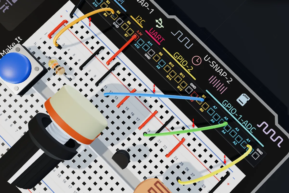
Connect a jumper wire from breadboard pin i26 to ADC pin A1 on the UNDA.Xplora board, next to pin 2 of the light sensor.
Connect a jumper wire from breadboard pin j19 to ADC pin A5 on the UNDA.Xplora board, next to the middle pin of the TMP36.
Connect a jumper wire from to breadboard pin j12 to Xplora ADC Pin B1, next to the middle pin of the potentiometer.
Connect a jumper wire from breadboard pin j3 to digital pin B5 on the UNDA.Xplora board.
Check out the virtual breadboarding for the same project at:
Dashboard
Run the Project
Power up your UNDA.Xplora, go to the Projects Menu and upload the Dashboard Project Project. Once the project is fully uploaded, open the Play Section and then:
- Press the sensor gently but firmly or you can also blow on it.
- Press the button and after sometime release it and then press it again.
- if its day time cover the light sensor and if its night time shine a flashlight on it.
- Turn the knob until the limit and then turn it in the opposite direction.
Observe what happens in Play Section as you do the above activities.
Refer to Xplora Menu - Projects on how to open and upload the project on your UNDA.Xplora.
Observation
The dashboard shows the temperature value in degrees and the light levels in percentage, updating in real time as the sensors respond to changes in the environment. For the potentiometer and pushbutton, the dashboard displays a graph that changes as the potentiometer is turned and when the button is pressed, showing how the input values vary over time.