Introduction
Is it hot outside? Feeling sticky and sweaty? Then it’s time to cool things down with your very own fan!
Fans are super " cool" inventions. With just one press of a button, the blades start spinning round and round, sending out a nice, cool breeze to make you feel fresh and happy.
Inside the fan, there's a small motor. When it turns on, it spins the blades and moves the air around you. That spinning is what moves the air and cools you down! It’s like having your own little wind.
Fans are found almost everywhere; at home, in school, in offices, buses, and even outside. Some are big and hang from the ceiling. Others are small and sit on a table. Even computers and cars use fans to stay cool!
In this fun project, you’ll build your own fan using a motor, some components, and cut-out paper for blades. Press the button and watch your blades spin!

Build the Project
In this section we will explore how to use UNDA.Xplora to build a simple electrical fan.
Components Used
| # | Name | Component | Qty | Description |
|---|---|---|---|---|
| 1 | Motor | 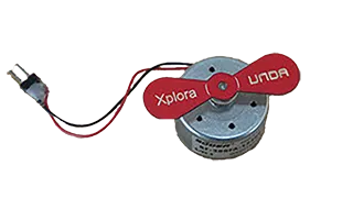 | 1 | DC Motor |
| 2 | Pushbutton | 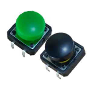 | 2 | Choose your preferred button color |
| 3 | Resistor | 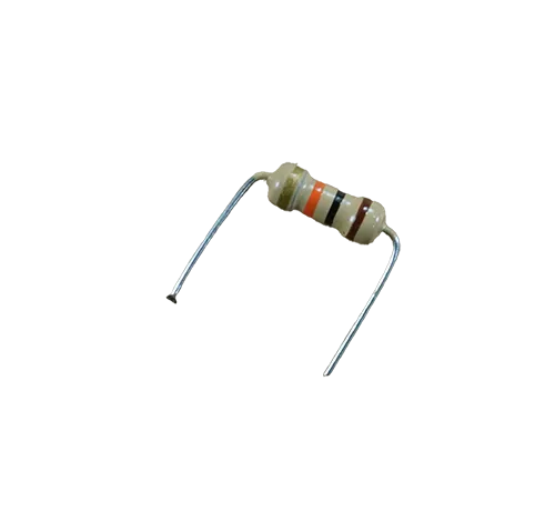 | 1 | 10 Kilo-Ohm Resistor |
| 4 | Jumper Wire | 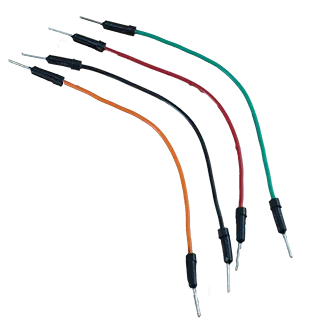 | 4 | Male-Male Jumper Wires |
| 5 | Breadboarding Wires | 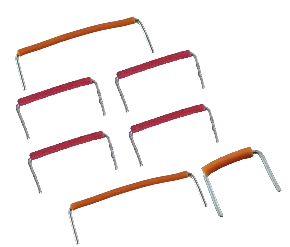 | 6 | Choose breadboarding wires that fit easily between connection points |
| 6 | Battery Connector | 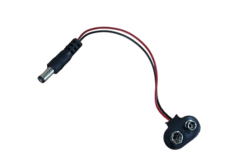 | 1 | 9V Battery Connector |
| 7 | Battery | 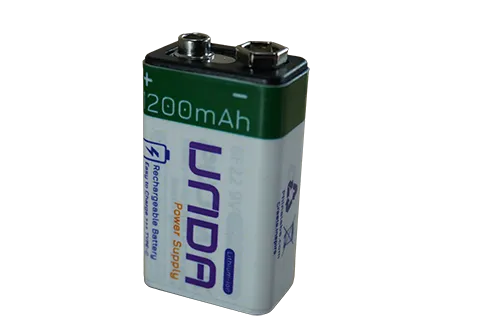 | 1 | UNDA 9V Rechargeable Battery |
| 8 | UNDA:Xplora | 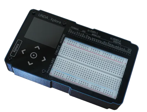 | 1 | Xplora Electronics Kit |
Step 1
Wiring overview of connecting the Push Buttons on the Breadboard
| From | Wire / Part | To | Note |
|---|---|---|---|
| Push Button 1 Pins | Push button 1 | Breadboard Pins (top-g4 & g6)(bottom-d4 & d6) | Places button 1 on the breadboard |
| Push Button 2 Pins | Push button 2 | Breadboard Pins (top-g14 & g16)(bottom-d14 & d16) | Places button 2 on the breadboard |
| Breadboard Pin h6 | Resistor 10,000 kΩ | Breadboard Pin h10 | Used as a pull-up resistor for button 1 |
| Breadboard Pin h16 | Resistor 10,000 kΩ | Breadboard Pin h20 | Used as a pull-up resistor for button 2 |
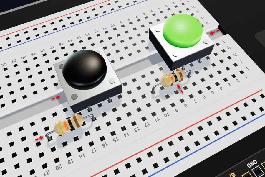
Insert the pushbutton with its top pins in breadboard pins g4 and g6, and its bottom pins in d4 and d6.
Insert the pushbutton with its top pins in breadboard pins g14 and g16, and its bottom pins in d14 and d16.
Insert the 10 kΩ resistor with one leg in h6 and the other in h10 of the breadboard.
Insert the 10 kΩ resistor with one leg in h16 and the other in h20 of the breadboard.
In this project, the 10 kΩ resistors are used as pull-up resistors. They keep the push button pins at a HIGH (3.3V) state when the buttons are not pressed, giving the kit a stable signal to read.
When a button is pressed, the pin is connected to GND, changing the signal to LOW.
Step 2
Connecting the Push buttons to 3.3V Power.
| From | Wire / Part | To | Note |
|---|---|---|---|
| Xplora 3.3V Pin | red | Top Positive Breadboard Rail | 3.3V Power supplied to top positive breadboard rail |
| Top Positive Breadboard Rail | orange | Breadboard Pin j10 | Supplies 3.3V power to button 1 |
| Top Positive Breadboard Rail | orange | Breadboard Pin j20 | Supplies 3.3V power to button 2 |
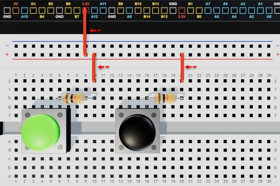
Connect a breadboarding jumper wire from any 3.3V pin on your kit to the top positive breadboard rail.
Connect a breadboarding jumper wire from the top positive breadboard rail to breadboard pin j10.
Connect a breadboarding jumper wire from the top positive breadboard rail to breadboard pin j20.
Step 3
Connecting the Push Buttons to Ground (GND).
| From | Wire / Part | To | Note |
|---|---|---|---|
| Top Negative Breadboard Rail | black | Xplora GND Pin | Connects bottom negative rail to Ground (GND) Connection |
| Top Negative Breadboard Rail | black | Breadboard Pin i4 | Connects the button 1 to Ground Connection |
| Top Negative Breadboard Rail | black | Breadboard Pin i14 | Connects the button 2 to Ground Connection |
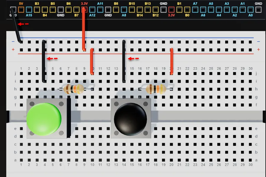
Connect a jumper wire from any GND pin on your kit to any pin of the top negative breadboard rail.
Run a breadboarding jumper wire from the top negative breadboard rail to breadboard pin i4.
Run a breadboarding jumper wire from the top negative breadboard rail to breadboard pin i14.
Step 4
Connecting the push buttons to Xplora digital pins.
| From | Wire / Part | To | Note |
|---|---|---|---|
| Xplora Pin B5 | green | Breadboard Pin i6 | Signal Jumper Wire for push button 1 |
| Xplora Pin B15 | blue | Breadboard Pin i16 | Signal Jumper Wire for push button 2 |
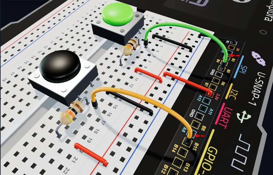
Connect a jumper wire from breadboard pin i6 to digital pin B5 on the UNDA.Xplora board.
Connect a jumper wire from breadboard pin i16 to digital pin B15 on the UNDA.Xplora board.
Step 5
Wiring overview of the DC Motor on the breadboard.
| From | Wire / Part | To | Note |
|---|---|---|---|
| Motor Positive Pin | Buzzer | Breadboard Pin b27 | Connects Positive Pin of Motor on the breadboard |
| Motor Negative Pin | Buzzer | Breadboard Pin b26 | Connects Negative Pin of Motor on the breadboard |
| Xplora Pin B0 | blue | Breadboard Pin e27 | Signal Jumper Wire |
| Top Negative Breadboard Rail | black | Breadboard Pin e26 | Connects the negative buzzer pin to Ground (GND) |
Take note that the motor has polarity meaning it has positive and negative terminal. The positive is marked by red wire and negative marked by black wire.
The two pins of the motor are positioned close to each other, so when you insert one pin, the other pin should fit easily into the adjacent hole on the breadboard.
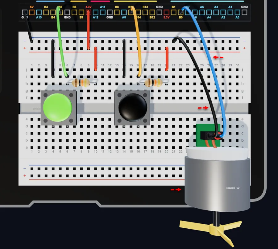
Insert the motor with the positive (+) leg in pin b27 and the negative (–) leg in pin b26 of the breadboard.
Connect a jumper wire from breadboard pin e27 to digital pin B0 on your kit.
Connect a jumper wire from breadboard pin e26 to any GND pin on your kit.
This step uses an image from the Xplora 3D Simulator. The motor are designed to simplify the connections for the simulation and it may look different from the actual Dc motor.
Even though the motor looks different, follow the instructions as given in this guide step when building the physical circuit.
Check out the virtual breadboarding for the same project at:
Fan
Run the Project
Once you are done building the project, power up your kit. Upload your project and then open the Play Section and press the push button and observe what happens.
You can refer to Xplora Menu - Projects to check out the steps of how to upload the project.
Observation
When the first pushbutton is pressed, it sends a signal to the system, telling it to supply power to the motor, which then causes it to start rotating (like a fan). This happens because the button acts as an input device, allowing your UNDA.Xplora kit to detect the press and respond accordingly.
The second pushbutton is used to control the fan’s speed. Each press cycles through three speed levels: low, medium, and high.
When the first pushbutton is pressed again, the motor stops, showing how the system uses button inputs to control actions. The fan also remembers the last selected speed, so when it is started again, it resumes at the speed that was previously set.
In the Play Section, you will see that this rotation has been animated to mimic that of an electric fan.