Introduction
Look around you for a second.
From your phone notifications to your TV... from M-Pesa shops to ambulances and police cars... tiny lights are everywhere.
They flash, blink, and shine to send messages, warn us, and grab our attention.
These small but powerful lights are called LEDs (say: ell-ee-dees).
LED stands for Light Emitting Diodes.
So, what makes LEDs so special?
- They are super bright
- They use very little electricity
- They come in many colours
That’s why you’ll find them almost everywhere around you.
You can learn more about LEDs here
But here’s the part most people don’t notice...These lights don’t just turn ON and OFF because someone flips a switch.
They are controlled digitally. A microcomputer code decides when the light turns ON, when it turns OFF, and how it behaves
And now, you’re going to learn how to do the same.
In the next sections, you’ll build your own flashing light using the UNDA Xplora and create a simple real-world project using craft materials.
But before you start building, let’s break it down into a few simple things you’ll explore:
Things you will explore
Switching a light ON and OFF digitally
Making a light blink
Switching a light ON and OFF digitally
Just like using a wall switch at home, we either allow electricity to pass or not thus turning the bulb ON or OFF.
An LED only turns ON when electricity flows through it, and turns OFF when that flow stops.
But instead of controlling it with our hands, we can use a computing device like the Unda.Xplora to create HIGH and LOW signals.
A HIGH signal means we are turning ON, allowing electricity to pass and a LOW means we turn off.
- Using the simulation below, turn the LED ON and OFF.
- Move the PWM control slider to change how bright the LED glows.
- Try different brightness levels and see what happens!
Try It: Control the LED
Making a light blink
Controlling a light is not just about turning it ON and OFF.
UNDA Xplora also has a TIMER that helps us control when signals are sent and how long they stay active.
When we keep sending HIGH and LOW signals again and again, the LED starts to blink
Using the UNDA Xplora;
A HIGH signal turns the LED ON.
The TIMER waits for a moment.
Then a LOW signal turns the LED OFF.
When this repeats again and again, the LED starts to blink.
Short timing creates fast blinking.
Longer timing creates slower blinking.
- Head back to the simulation above and enable the blink timer.
- Experiment with different timing intervals to control the blinking speed of the LED.
- Can you make it blink very slowly? What about very fast?
Now challenge yourself
See if you can answer the questions below about LEDs
Quiz
1What makes an LED turn ON?
2Which two signals does the UNDA Xplora use to control an LED?
3What helps control how long the LED stays ON or OFF?
4What happens when HIGH and LOW signals repeat again and again?
Now that you understand how to switch an LED ON and OFF, and how to make it blink!
It’s time to put these ideas into action.
Build the Project
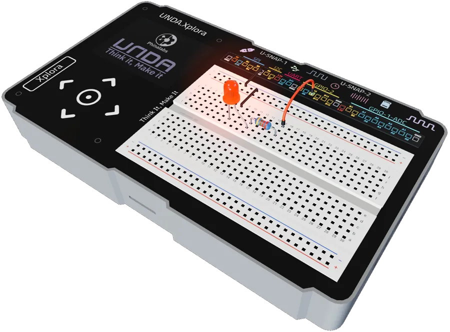
In this section, you’ll build your own flashing light project using the Unda.Xplora on the breadboard
As you build, pay attention to:
- How the LED switches ON and OFF
- How the TIMER changes the blinking speed
Then explore the Play Section and try different options like:
- Fast blink
- Slow blink
- Notification
Observe the patterns and speed carefully.
What changes?
What stays the same?
What do you notice?
Let's get started!
Components you will use
| # | Name | Component | Qty | Description |
|---|---|---|---|---|
| 1 | LED | 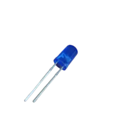 | 1 | Blue Colored LED |
| 2 | Resistor |  | 1 | 220 Ohm Resistor |
| 3 | Jumper Wire | 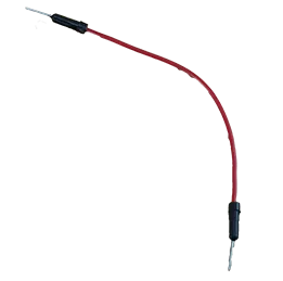 | 1 | Male-Male Jumper Wires |
| 4 | Breadboarding Jumper Wire | 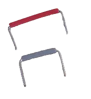 | 2 | Small-sized breadboarding wire |
| 5 | Battery Connector | 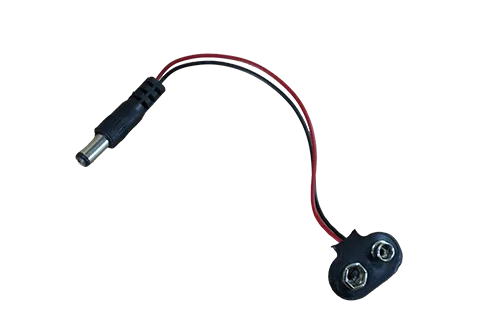 | 1 | 9V Battery Connector |
| 6 | Battery | 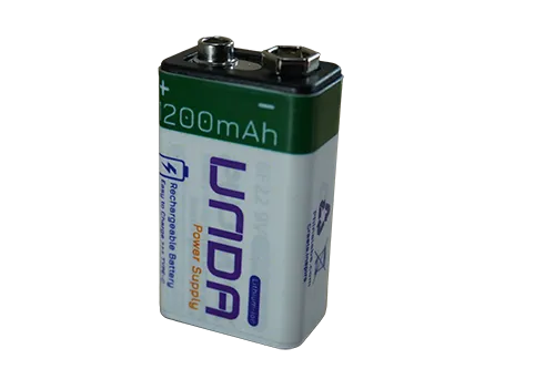 | 1 | UNDA 9V Rechargeable Battery |
| 7 | UNDA:Xplora | 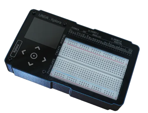 | 1 | Physical Computing Kit |
Circuit Connections
A preview of how the components are wired on the breadboard
| From | Wire / Part | To | Note |
|---|---|---|---|
| Breadboard Pin c14 | LED Blue | Breadboard Pin c17 | Connecting LED on Breadboard |
| Breadboard Pin e17 | Resistor 220 Ohms | Breadboard Pin g17 | Current resistor |
| Xplora Pin B15 | white | Breadboard Pin i17 | Signal wire |
| Xplora GND Pin | black | Bottom Negative Rail | Crates GND for circuit |
| Bottom Negative Rail | black | Breadboard Pin a14 | Connects LED to GND |
Step 1
Placing an LED on the breadboard
| From | Wire / Part | To | Note |
|---|---|---|---|
| Positive Pin | LED Blue LED | Breadboard Pin g11 | Places positive pin of the LED on the breadboard |
| Positive Pin | LED BLUE LED | Breadboard Pin cg8 | Places negative pin of the LED on the breadboard |
LEDs have polarity which means they have positive and a negative terminal leg. The positive leg is the longer one and the negative leg is the shorter one.
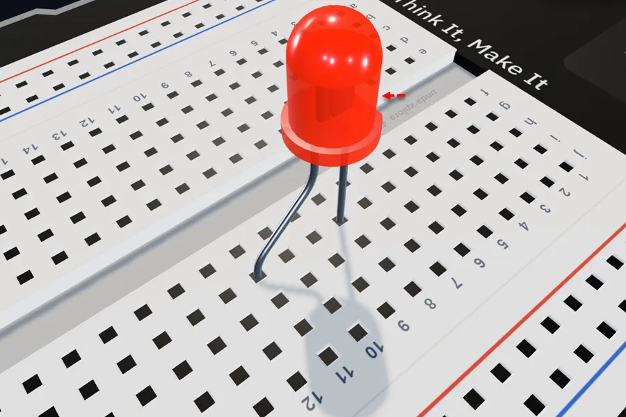
Insert an LED (any color) into the breadboard with the negative leg in g8 and the positive leg in g11.
Step 2
Connecting a 220 ohm Resistor on the Breadboard.
| From | Wire / Part | To | Note |
|---|---|---|---|
| Breadboard Pin h11 | Resistor 220 ohm | Breadboard Pin h15 | Connecting resistor on the breadboard |
Resistors do not have polarity, so they can be inserted in either direction. They are used with LEDs to limit the amount of current flowing through the LED, protecting it from damage.
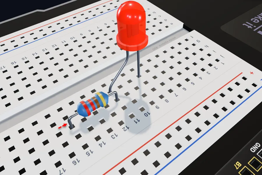
Insert the 220 ohm resistor with one leg in h11 (next to the LED's positive leg) and the other in h15, as shown.
Step 3
Connect the jumper wire to digital output
| From | Wire / Part | To | Note |
|---|---|---|---|
| Xplora Pin B15 | red | Breadboard Pin j15 | Signal Jumper Wire |
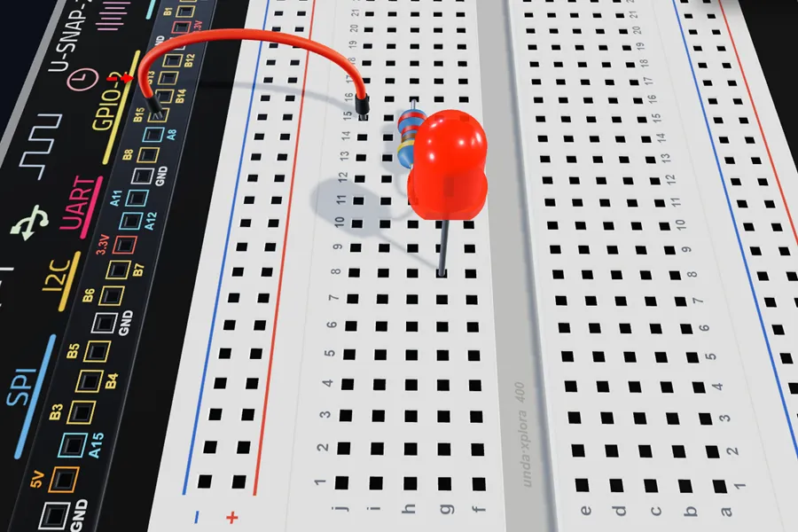
Connect a jumper wire from breadboard pin j15 to digital pin B15 on the UNDA.Xplora board.
Step 4
Connecting the circuit to GND (Ground).
| From | Wire / Part | To | Note |
|---|---|---|---|
| Xplora GND Pin | black | Top Negative Breadboard Rail | Circuit GND Connection |
| Top Negative Breadboard Rail | black | Breadboard Pin j8 | Connects LED to GND |
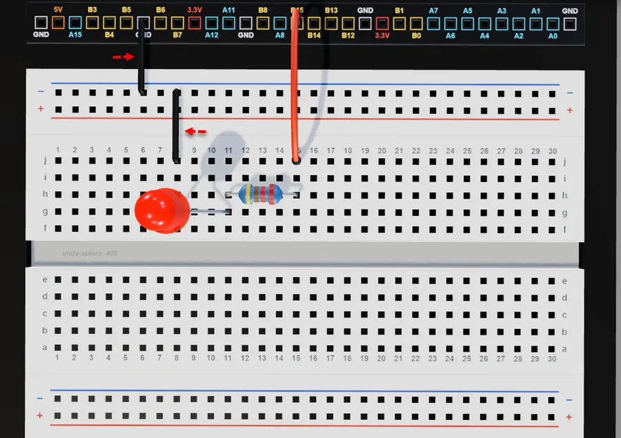
Connect a breadboarding jumper wire from the GND pin on your kit to the top negative breadboard rail.
Connect a breadboarding jumper wire from the top negative breadboard rail to breadboard pin j8.
Explore the project in 3D using the interactive virtual UNDA.Xplora kit:
Flashing Light
Run the Project
Once you are done building the project, connect the battery to the the battery connector and then plug it to the power port of your UNDA.Xplora to power it on. Remember you can also use a USB-C Cable to power up your kit.
Once your kit is powered on, go to the Project Menu Window and then upload the Flashing Light Project and open the Play Section. Try put the different options on the Play Section and observe what happens.
Refer to Xplora Menu - Projects on how to open and upload the project on your UNDA.Xplora.
Observation
Once the project has uploaded and is running, you will first observe the LED flashing at 500 milliseconds ON and 500 milliseconds OFF. The LED is turned ON and OFF by these timing intervals, creating a simple, regular blink that repeats as long as the power is on.
In the Play Section, you can select different flash patterns to see how changing the timing creates different effects. These include Fast Blink, Slow Blink, Heartbeat, Ticker, and Notify.
For example, the Fast Blink pattern uses short ON and OFF times, making the LED flash quickly, while Slow Blink uses longer timing intervals, making the LED flash more slowly.
Other patterns create different visual effects using their own timing sequences:
- Heartbeat – the LED flashes in a rhythm similar to a heartbeat.
- Ticker – the LED follows a repeated timing sequence to create a ticker-like effect.
- Notify – the LED uses a distinct timing pattern to indicate a notification.
The timing of each ON and OFF period determines how the LED appears to flash, allowing the same LED to produce several different patterns.
If the LED does not flash, make sure you have connected the circuit correctly.
Once you are done, Power the board using the battery or using the type-C cable and upload the flashing light project and observe what happens.
You can also select the various options on Play section and bserve whta happens.
Knowledge Check
1How many milliseconds does LED flash on and off for 1 second interval?
2What turns ON or OFF an LED at set intervals