Introduction
Did you know that the right kind of light can actually help you study better?
It’s true! Good lighting helps your brain take in information more easily, while bad lighting can slow you down and even cause eye strain, headaches, or trouble focusing.
Too dim, and your eyes work extra hard just to read.
Too bright, and the glare can make it tough to concentrate.
That’s why choosing just the right brightness is very important whether you're reading, relaxing, or getting ready for bed.
In this project, you’ll learn how to build your very own light dimmer that lets you control the brightness with a twist of a knob. Just like turning the volume up or down... but this time, it’s for light!
Let’s build a light dimmer and find the right light for your study zone!
Build the Project
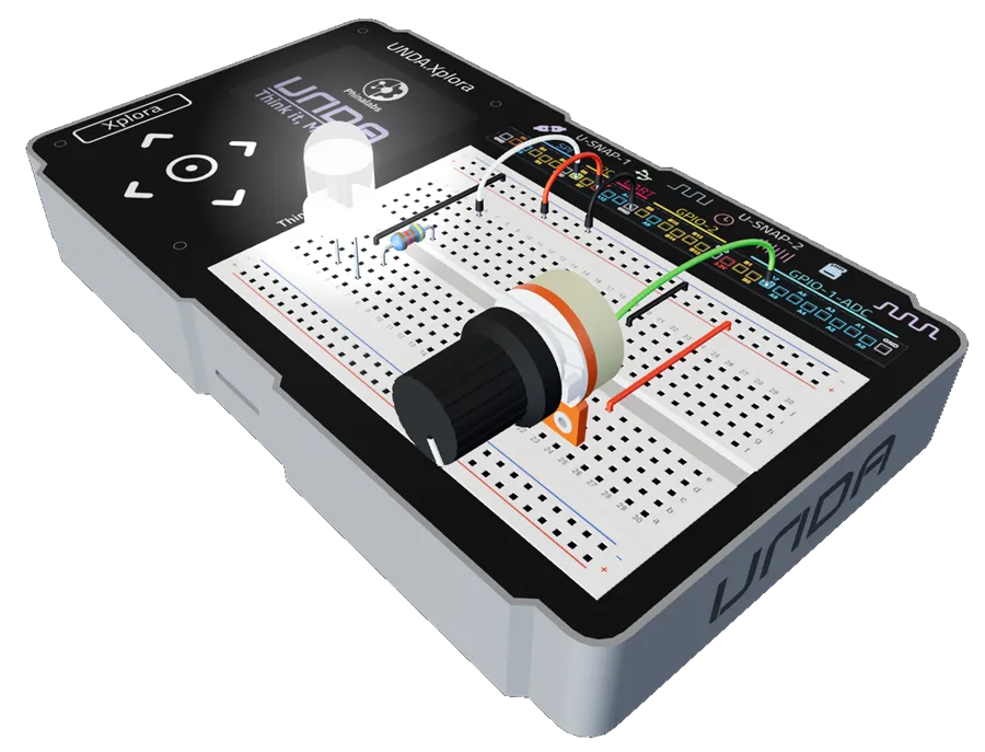
Let’s now move on to building the Light Dimming Project on the UNDA.Xplora breadboard, where you will set up the circuit and learn how to control the brightness of an LED using a potentiometer.
Components Used
| # | Name | Component | Qty | Description |
|---|---|---|---|---|
| 1 | LED | 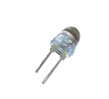 | 1 | White Colored LED. |
| 2 | Resistor |  | 1 | 220 Ohm Resistor |
| 3 | Jumper Wire | 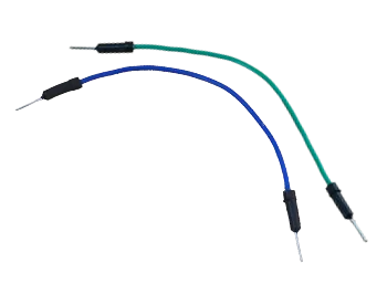 | 2 | Male-Male Jumper Wires |
| 4 | Breadboarding Wires | 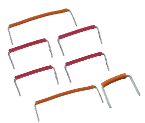 | 6 | Choose breadboarding wires that fit easily between connection points |
| 5 | Battery Connector | 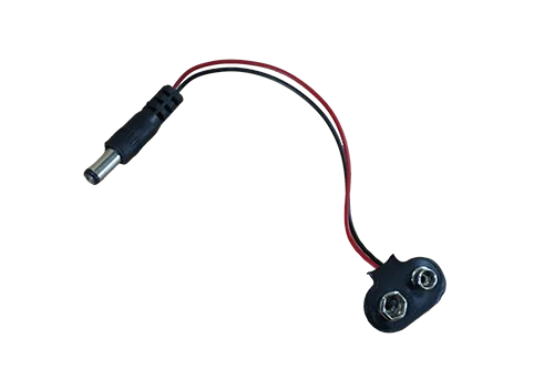 | 1 | 9V Battery Connector |
| 6 | Battery | 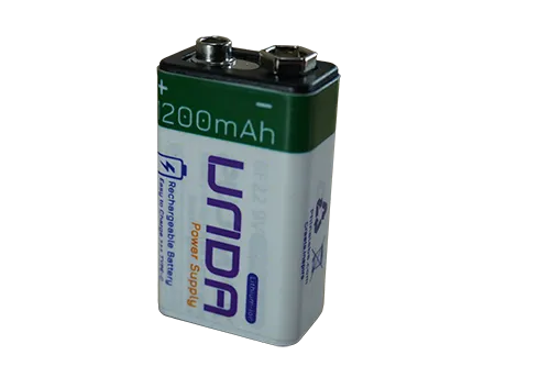 | 1 | UNDA 9V Rechargeable Battery |
| 7 | UNDA:Xplora | 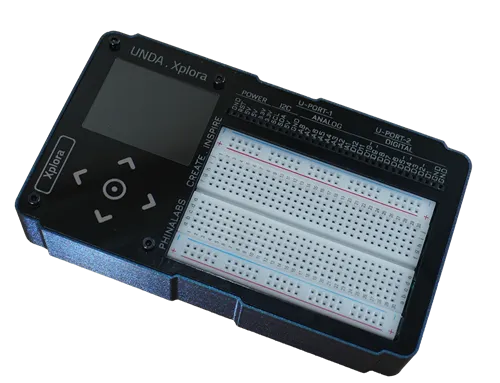 | 1 | Xplora Electronics Kit |
Step 1
Wiring the White LED on the breadboard.
| From | Wire / Part | To | Note |
|---|---|---|---|
| Positive Pin | LED | Breadboard Pin b6 | Connects Positive Pin of buzzer on the breadboard |
| Negative Pin | LED | Breadboard Pin b4 | Connects Negative Pin of buzzer on the breadboard |
| Breadboard Pin e6 | Resistor 220 Ohm | Breadboard Pin g6 | Current-limiting resistor |
| Xplora Pin B6 | white | Breadboard Pin i6 | Signal Jumper Wire |
| Xplora GND Pin | red | Top Negative Rail | Connect GND to the Top Negative Breadboard |
| Top Negative Rail | black | Breadboard Pin e4 | Connect GND to the LED |
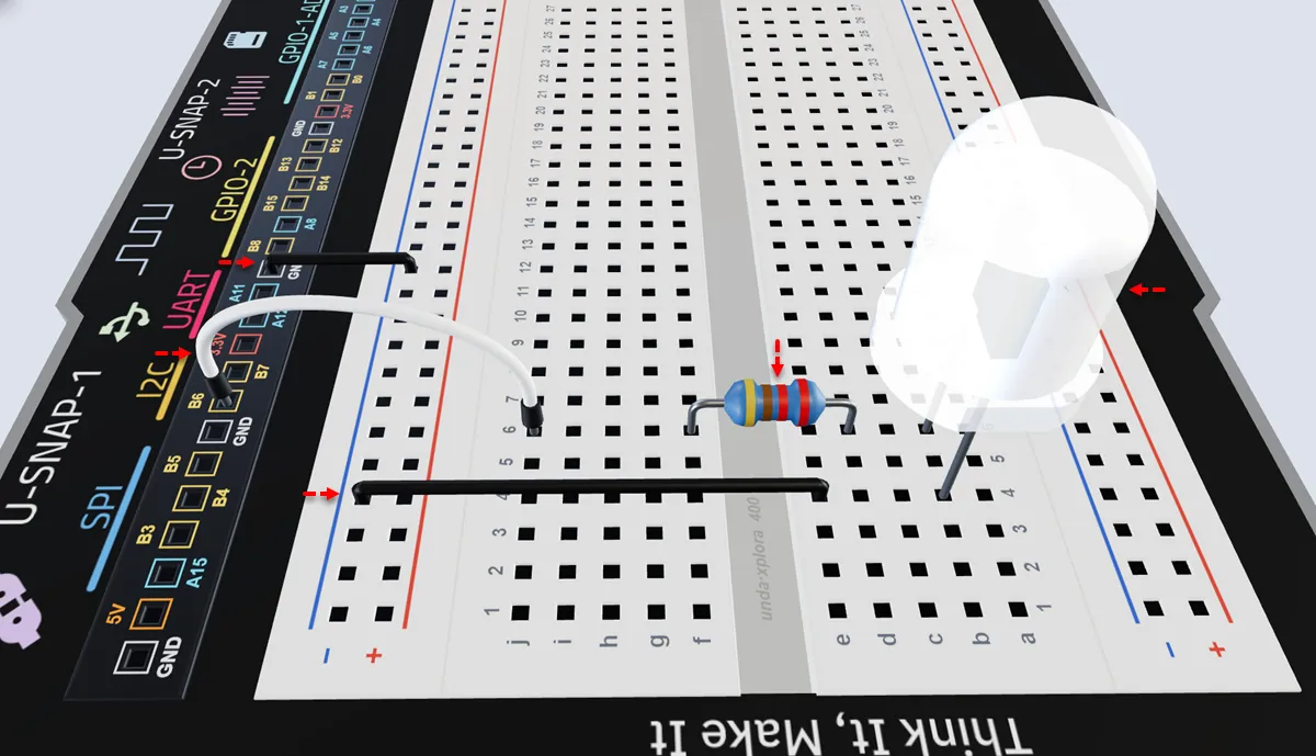
Insert the LED with the positive (+) leg in pin b6 and the negative (–) leg in pin b4 of the breadboard.
Insert the 220-ohm resistor with one leg in pin d6 and the other leg in pin f6 of the breadboard."
Connect a jumper wire from breadboard pin i6 to digital pin B6 on your kit.
Connect a breadboarding jumper wire from any GND Pin of the kit to the top negative breadboard rail.
Connect a jumper wire from top negative rail to breadboard e4 to connect the LED to GND.
Step 2
Placing the Potentiometer on the breadboard
| From | Wire / Part | To | Note |
|---|---|---|---|
| Potentiometer Pin 1 | Potentiometer | Breadboard Pin b20 | Connects potentiometer pin 1 on the breadboard |
| Potentiometer Pin 2 | Potentiometer | Breadboard Pin b22 | Pin 2 is the potentiometer's signal pin |
| Potentiometer Pin 3 | Potentiometer | Breadboard Pin b24 | Connects potentiometer pin 3 on the breadboard |
The three pins on the potentiometer are evenly spaced. Once Pin 1 is in b20, Pin 2 and Pin 3 will easily insert into b22 and b24.
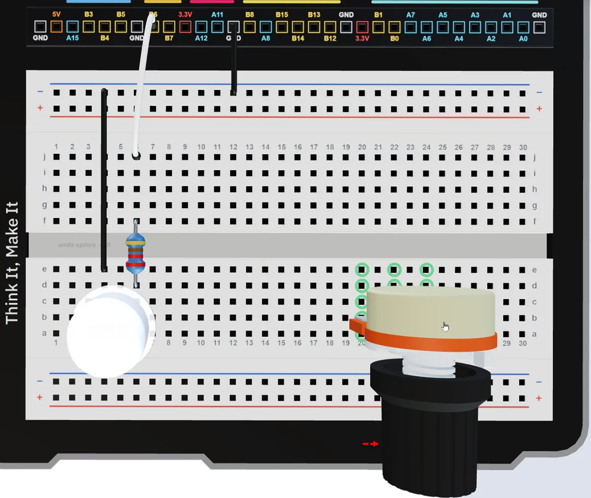
Place the potentiometer into the breadboard with Pin 1 in b20, Pin 2 in b22 (signal pin), and Pin 3 in b24.
Step 3
Connecting the potentiometer to 3.3v and Ground
| From | Wire / Part | To | Note |
|---|---|---|---|
| Xplora 3.3V Pin | red | Top Positive Breadboard Rail | Provides 3.3V to the top positive breadboard rail |
| Top Positive Breadboard Rail | red | Breadboard Pin e24 | Supplies 3.3V to potentiometer Pin 3 |
| Top Negative Breadboard Rail | black | Breadboard Pin i20 | Provides GND to the potentiometer circuit |
| Breadboard Pin g20 | black | Breadboard Pin e20 | Connects GND to potentiometer Pin 1 |
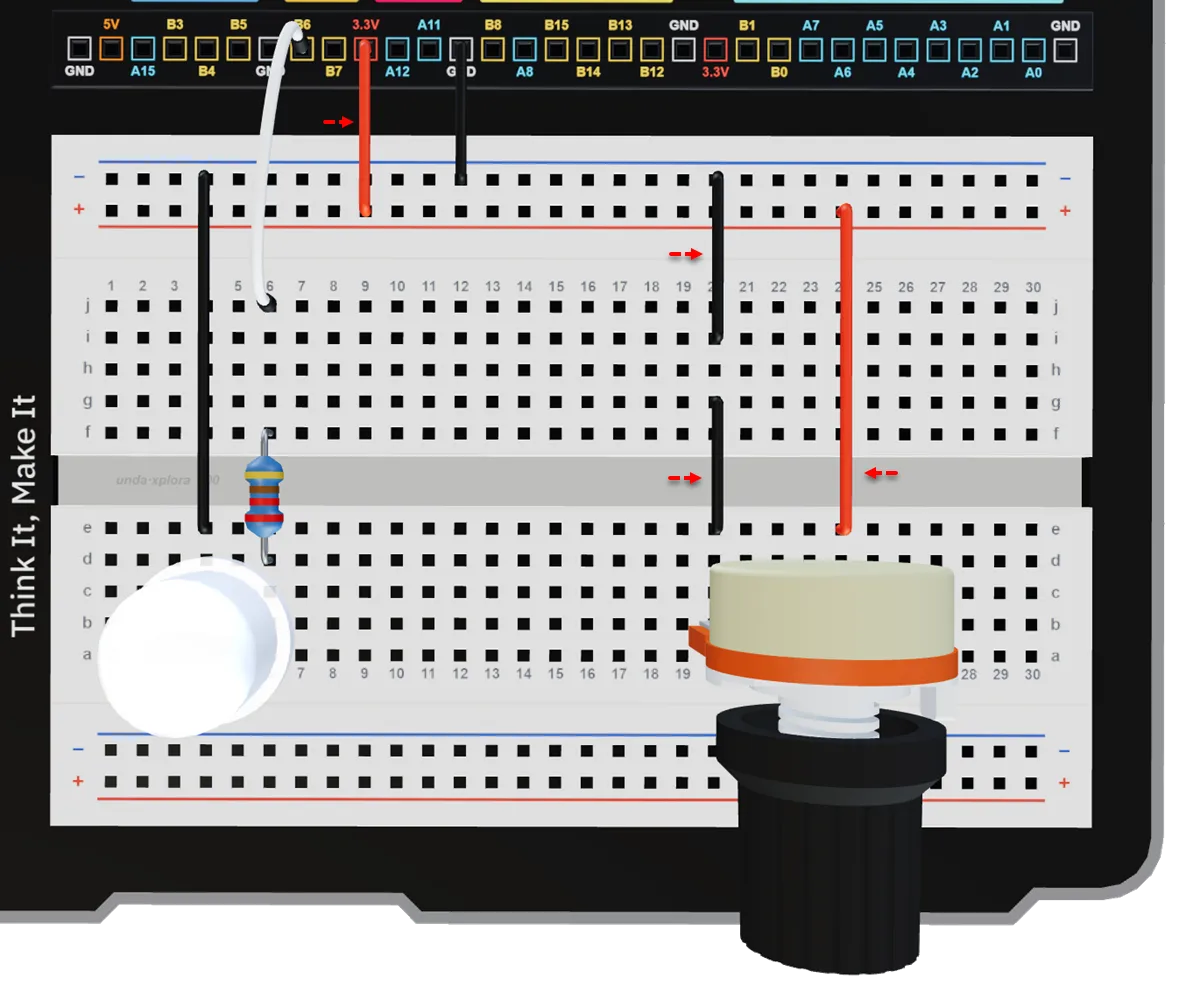
Connect a breadboarding jumper wire from the 3.3V pin on your kit to the top positive breadboard rail.
Connect a breadboarding jumper wire from the top positive breadboard rail to breadboard pin e24.
Connect a breadboarding jumper wire from the top negative breadboard rail to breadboard pin i20.
Connect a jumper wire from g20 to e20 to connect Pin 1 of the potentiometer to GND.
The potentiometer will still work if the 3.3V and GND connections are swapped. However, the direction of rotation will be reversed, so turning the knob clockwise will decrease the reading instead of increasing it (and vice versa).
Step 4
Connecting the Potentiometer to an ADC-capable Pin.
| From | Wire / Part | To | Note |
|---|---|---|---|
| Xplora ADC Pin A7 | green | Breadboard Pin e22 | Signal Jumper Wire |
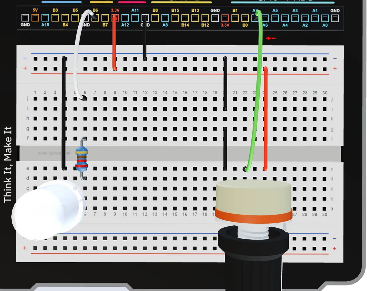
Connect a jumper wire from to breadboard pin e22 to Xplora ADC Pin A7.
Run the Project
Power your UNDA.Xplora and upload the Light Dimming Project. Once fully loaded, open the Play Section and turn the knob of the potentiometer while simultaneously observing change in Play section as well as the LED Brightness.
You can always refer to Xplora Menu - Projects to learn how to load the project on your UNDA.Xplora.
The ADC pin reads the changing voltage from the potentiometer, allowing the kit to measure the position of the knob and use it to control things like LED brightness, buzzer volume, or motor speed.
Observation
At each position of the potentiometer, a different analog voltage level is produced. This voltage is sent to the Xplora ADC Pin A7.
The ADC (Analog-to-Digital Converter) reads this changing voltage and converts it into a corresponding digital value.
This digital value is then used to control the brightness of the LED:
- Higher ADC value → brighter LED
- Lower ADC value → dimmer LED
As you rotate the potentiometer, the ADC continuously updates this value in real time, which is why both the LED brightness and the room lighting in the Play Section change smoothly.
Explore the virtual version of this project in the Xplora 3D app:
Light Dimming