Introduction
When the night falls, we need lights to help us see in the dark. Lights make it possible to see things at night, just like the sun during the day. When evening comes and its starts to get dark, we usually flip or press a switch to fill light in the room and continue with our important work.
A switch is the way we communicate with the lights, to tell them when to go on and when to go off. They are a staple not just in our homes but in buildings all around the world.
A light switch is a simple device that is used to control home lighting system. It is usually fixed in a wall and can either be pressed or flipped to turn on or turn off electric light.
Things to learn
In this lesson, you will learn about:
How a switch works
How to build a simple light switch
How a switch works
Switches are simple devices that control the flow of electricity in a circuit. They act like a gate that can be opened or closed.
When a switch is closed it allows electricity to flow through to turn on the bulb and when it is opened it stops the flow and turns off the bulb.
Build the project
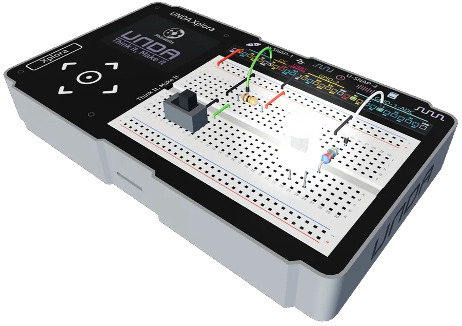
In this section, we will build the Light switch project on our UNDA.Xplora Breadboard.
Components Used
| # | Name | Component | Qty | Description |
|---|---|---|---|---|
| 1 | LED | 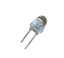 | 1 | White Colored LEDs |
| 2 | Slide Switch | 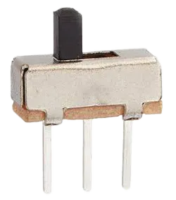 | 1 | Single Pole Double Throw type of slide switch. |
| 3 | Resistor |  | 1 | 220 Ohm Resistor |
| 4 | Resistor | 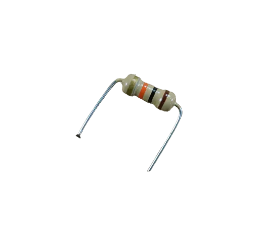 | 1 | 10Kilo-ohm Resistor |
| 5 | Jumper Wire | 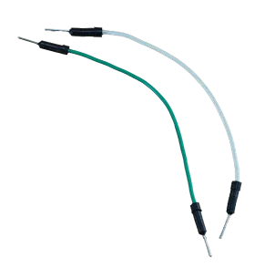 | 2 | Male-Male Jumper Wires |
| 6 | Breadboarding Jumper Wire | 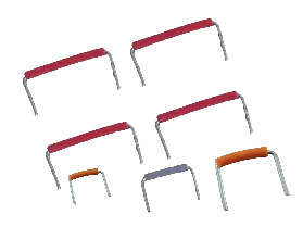 | 7 | Different-sized breadboarding wire |
| 7 | Battery Connector | 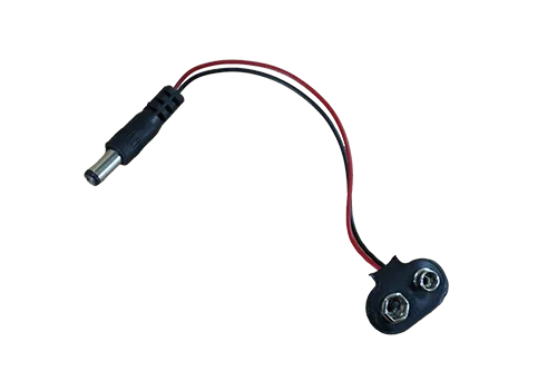 | 1 | 9V Battery Connector |
| 8 | Battery | 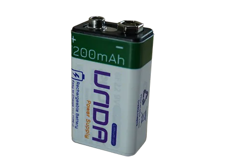 | 1 | UNDA 9V Rechargeable Battery |
| 9 | UNDA:Xplora | 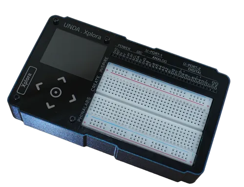 | 1 | Xplora Electronics Kit |
Step 1
Wiring the White LED on the breadboard.
| From | Wire / Part | To | Note |
|---|---|---|---|
| Xplora A5 | white | Breadboard Pin i25 | Signal Jumper Wire |
| Breadboard Pin e25 | Resistor 220 Ohms | Breadboard Pin f25 | Through-Hole Current resistor |
| Breadboard Pin b23 | White LED | Breadboard Pin b25 | Connecting the LED on the Breadoard. |
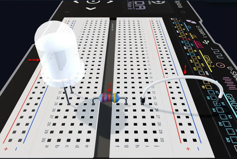
Insert a White LED with the short leg (–) into pin b23 and the long leg (+) in pin b25 of the breadboard.
Insert the 220 ohm resistor with one leg in e25 (next to the LED's positive leg) and the other in f25, as shown.
Connect a jumper wire from breadboard pin i25 to digital pin A5 on the UNDA.Xplora board.
Step 2
Placing the Slide Switch on the breadboard.
| From | Wire / Part | To | Note |
|---|---|---|---|
| Slide Switch Pins | Slide Switch SPDT | Breadboard Pins b5, b7 & b9 | Places button on the breadboard |
| Breadboard Pin h9 | Resistor 10,000 kΩ | Breadboard Pin h13 | Used as a pull-up resistor |
| Breadboard Pin e9 | green | Breadboard Pin f9 | Helps to extend Signal jumper wire Connection |
| Xplora Pin B6 | green | Breadboard Pin j9 | Signal jumper wire |
The slide switch has three pins: one common (COM) pin and two switched pins (L1 and L2).
In this guide, the COM pin is connected to GND, and only one of the switched pins (L1 or L2) is connected to a digital input pin for this project.
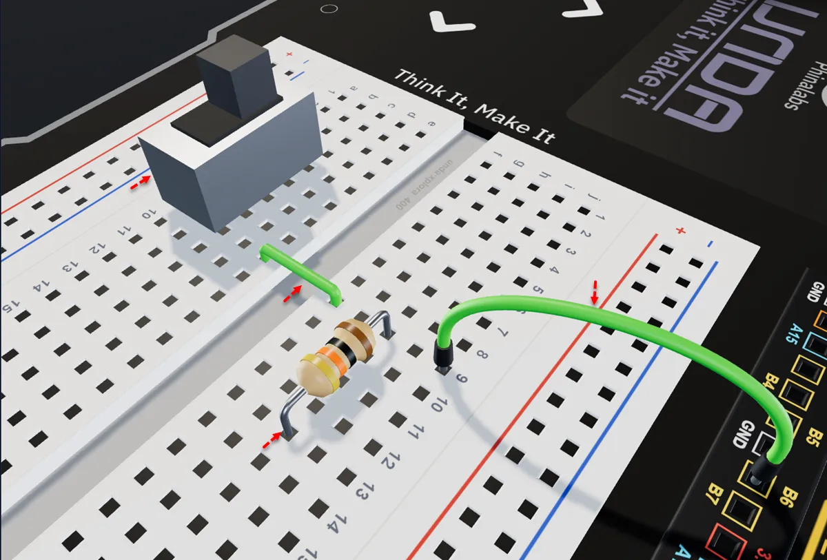
Insert the slide switch with its pins into breadboard pins b5, b7 and b9.
Insert the 10 kΩ resistor with one leg in h9 and the other in j9 of the breadboard.
Run a breadboarding wire from breadboard pin e9 to f9 to extend the connection from the signal wire.
Connect a jumper wire from breadboard pin j9 to digital pin B6 on your kit.
Step 3
Connecting the Slide Switch to 5V Power.
| From | Wire / Part | To | Note |
|---|---|---|---|
| Xplora 3.3V Pin | red | Top Positive Breadboard Rail | 3.3V power supplied to the positive rail |
| Top Positive Breadboard Rail | red | Breadboard Pin i13 | 5V power supplied to the Slide Switch |
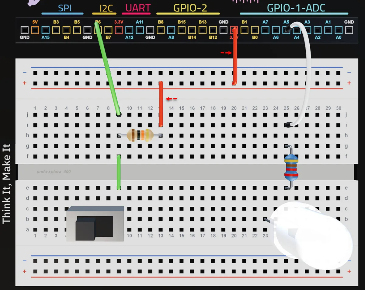
Connect a breadboarding jumper wire from any 3.3V pin on your kit to the top positive breadboard rail.
Connect a breadboarding jumper wire from the top positive breadboard rail to breadboard pin i13 to provide power to the slide switch.
Step 4
Connecting the circuit to Ground (GND).
| From | Wire / Part | To | Note |
|---|---|---|---|
| Xplora GND Pin | black | Top Negative Breadboard Rail | Connecting Negative Rail to Ground(GND) |
| Top Negative Breadboard Rail | black | Breadboard Pin h7 | Connects Breadboard column 7 to GND |
| Breadboard Pin e7 | black | Breadboard Pin f7 | Connect Slide Switch to GND to complete its circuit |
| Top Negative Breadboard Rail | black | Breadboard Pin j23 | Connects Breadboard column 23 to GND |
| Breadboard Pin f23 | black | Breadboard Pin e23 | Connects the LED to GND to complete the circuit |
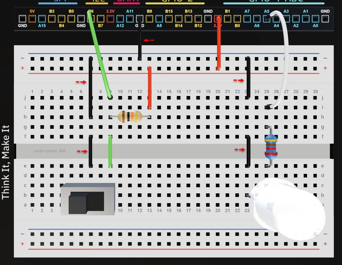
Connect a breadboarding jumper wire from the GND pin on your kit to the top negative breadboard rail.
Connect a breadboarding jumper wire from the top negative breadboard rail to breadboard pin h7.
Connect a jumper wire from f7 to e7 to extend and connect the Slide Switch to ground.
Connect a breadboarding jumper wire from the top negative breadboard rail to breadboard pin j23.
Connect a jumper wire from f23 to e23 to extend and connect the LED to ground.
Check out the simulation for the same project in the Xplora 3D app:
Light Switch
Run the Project
Power up your UNDA.Xplora using either the UNDA Battery or using the USB-C Cable. Once powered up, upload the Light Switch Project from the Project Menu and press the slide the switch.
Press the button again and observe what happens in the Play Section.
You can always refer to Xplora Menu - Projects to learn how to load the project on your UNDA.Xplora.
Observation
When we run our project, we observe that the LED is off and stays off until we move the SPDT switch to the other position, which turns the LED on. Moving the switch back returns the LED to the off state.
Why is this so?
Just like the light switches in our homes that turn lights on and off, the SPDT switch can be used to control the LED. When we first connect and run the project, the LED is in the OFF state.
Although it is connected and able to light up, our mini-computer tells the LED to stay off by sending a signal 0. Moving the SPDT switch to the other position sends a signal to our mini-computer to send signal 1 to the LED, causing it to turn on.
Moving the switch back changes the signal to 0, turning the LED off. Each time the SPDT switch is moved between its two positions, the signal changes, allowing the switch to control the LED.