Introduction
I bet we all love holidays. Christmas is my favorite holiday of the year. We love Christmas because we get to travel to our hometowns, spend time with loved ones and eat lots of delicious foods…..but what I like about Christmas is the decorations; the colorful ribbons, flowers, balloons and my favorite… the Christmas running lights.
With these lights put up in our homes, shops, supermarkets, malls and public places, they are very eye catching and mind blowing as they run around in different patterns.
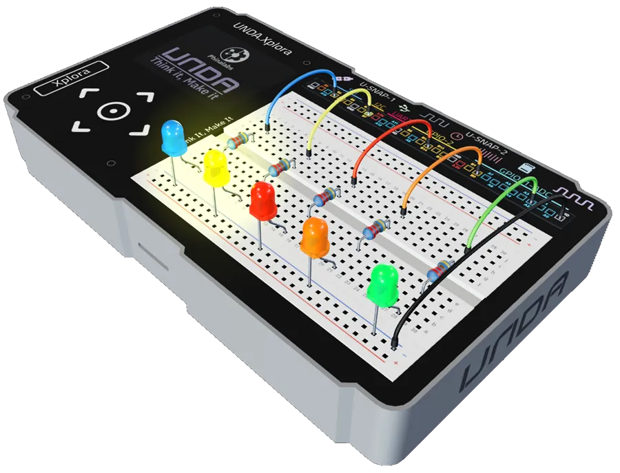
Christmas running lights also known as LED chasers are built in such a way that multiple LEDs flash on and off for a period of time, forming different patterns such as scrolling, dimming and when looked carefully, they look like they are chasing each other in one direction.
Things to Learn
In this lesson you will learn :
Digital Loops
Connecting Multiple LEDs
Digital control
Digital Loops
What is a loop?
A loop, just like the name suggests is an instruction that repeats again and again. Unlike human beings, a computer never gets tired or bored and can keep doing a certain task no matter how many times you tell it.
When you need to repeat the same instruction over and over again, we use a loop. A loop can repeat an instruction for a number of times or until a certain condition is met.
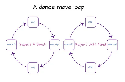
In Flashing Light Project, we learnt that a computer sends digital instructions of 1’s and 0’s; that is ON and OFF.
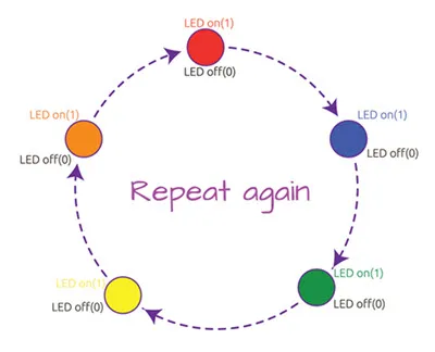
Hence, a digital loop is an ON(1) and OFF(0) instruction that repeats again and again. In our running lights project, the LEDs will turn on and off and repeat again and again.
Connecting Multiple LEDs
In the first project, we connected a single LED through a battery and a resistor
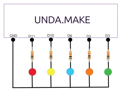
For multiple LEDs, the circuit is a bit different but the same rules apply. To connect our multiple LEDs, we connect each LED to a battery power supply through a resistor as in the diagram below.
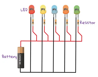
To switch the multiple LEDs ON and OFF repeatedly, we connect the LEDs to multiple digital pins on the UNDA.Xplora to send on and off instructions.
Digital Control
In this project, UNDA.Xplora acts like a 'tiny boss' that tells each LED what to do. It sends simple instructions-like “turn ON” or “turn OFF”-to each LED one at a time.
The LEDs light up one after another in a sequence; Red, Yellow, Blue, Orange, then Green. Each LED turns on, waits for a moment, then turns off before the next one lights up. Once the Green LED turns off, the pattern repeats again from the Red LED, creating a running lights effect.
Check out this sample Code for Running Lights project using UNDA.Atlas:
1repeat 3 times:
2  undaPlay LED white ON
3  wait 0.5 seconds
4  undaPlay LED white OFF
5
6  undaPlay LED green ON
7  wait 0.5 seconds
8  undaPlay LED green OFF
9
10  undaPlay LED Blue ON
11  wait 0.5 seconds
12  undaPlay LED Blue OFF
13
14  undaPlay LED Yellow ON
15  wait 0.5 seconds
16  undaPlay LED Yellow OFF
17
18  undaPlay LED red ON
19  wait 0.5 seconds
20  undaPlay LED red OFF
21
22
23// Multiple LEDs on
24undaPlay LED white OFF
25undaPlay LED red OFF
26undaPlay LED green OFFTry to run the code on Unda:Atlas and observe what happens when you open the UNDA.Play Simulator within the application.
UNDA.Xplora Digital Output
Before we build the project, its important to know the digital pins for each LED. We will use digital output pins 3, 5, 6, 10 and 11. These pins will each send a 1 or 0 to the LEDs connected to them.
- Pin D3 will send ON and OFF to Green LED.
- Pin D5 will send ON and OFF to Orange LED.
- Pin D6 will send ON and OFF to Blue LED.
- Pin D10 will send ON and OFF to Yellow LED.
- Pin D11 will send ON and OFF to Red LED.
Build the Project
In this section we are going to build the Running Lights Circuit on the UNDA.Xplora breadboard.
Components Used
| # | Name | Component | Qty | Description |
|---|---|---|---|---|
| 1 | LED | 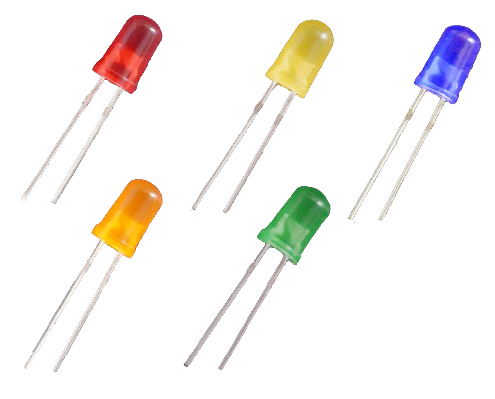 | 5 | Blue,Red,Yellow,Orange,Green Colored LEDs |
| 2 | Resistor | 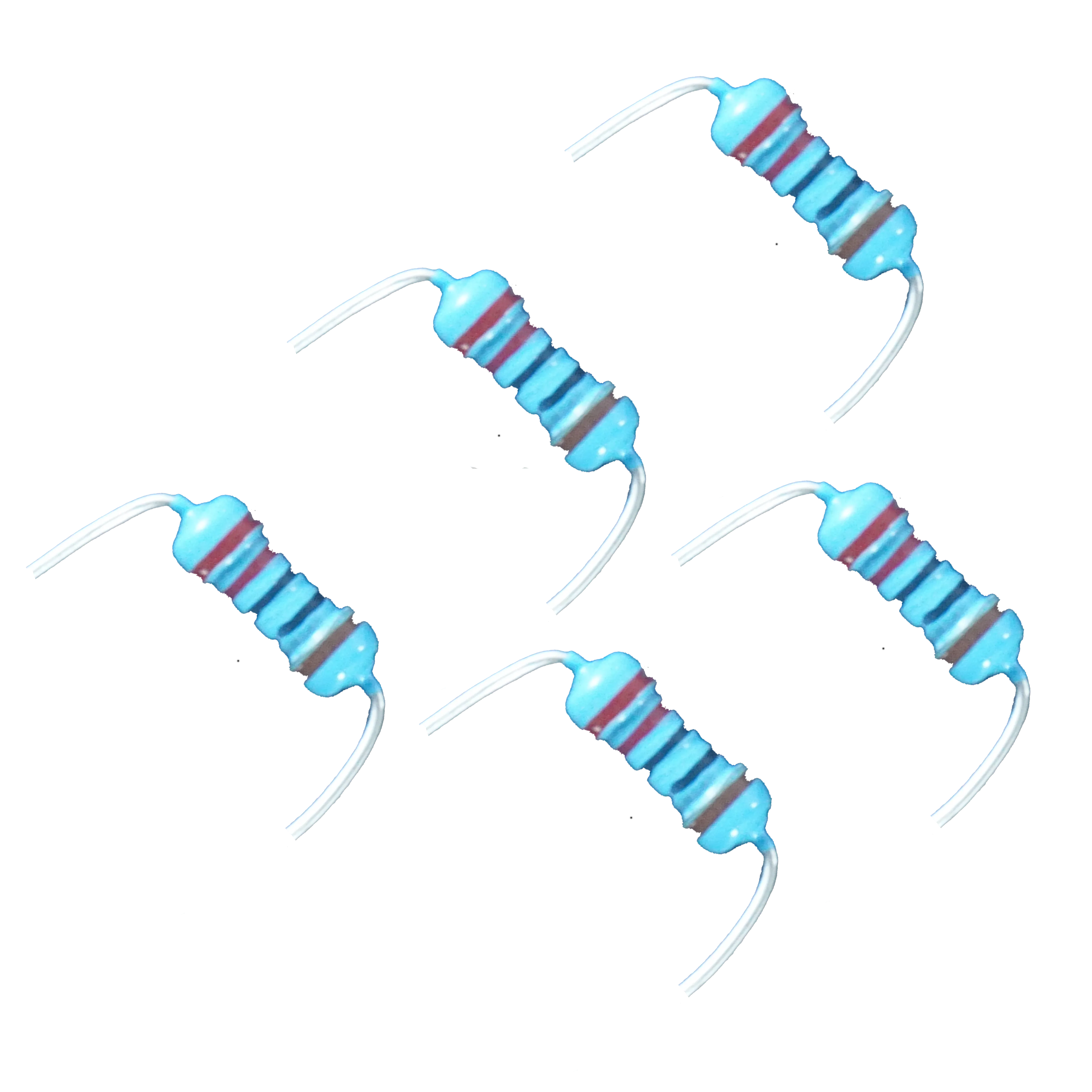 | 5 | 220 Ohm Resistor |
| 3 | Jumper Wire |  | 6 | Male-Male Jumper Wires |
| 4 | Battery Connector | 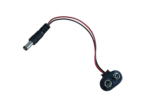 | 1 | 9V Battery Connector |
| 5 | Battery | 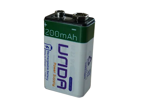 | 1 | UNDA 9V Rechargeable Battery |
| 6 | UNDA:Xplora | 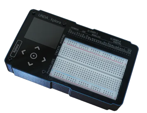 | 1 | Xplora Electronics Kit |
Step 1
A preview of how to wire the Green LED on the Breadboard.
| From | Wire / Part | To | Note |
|---|---|---|---|
| Xplora Pin A2 | green | Breadboard Pin h28 | Signal Jumper Wire |
| Breadboard Pin d28 | Resistor 220 Ohms | Breadboard Pin f28 | Through-Hole Current resistor |
| Breadboard a28 | Green LED | Breadboard Bottom GND | Connecting LED Negative to GND |
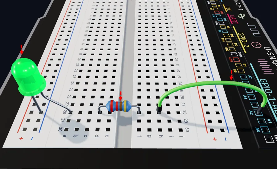
Insert a Green LED with the short leg (–) in the bottom negative rail and the long leg (+) in pin a28, as shown.
Insert the 220 ohm resistor with one leg in d28 (next to the LED's positive leg) and the other in f28, as shown.
Connect a jumper wire from breadboard pin h28 to digital pin B0 on the UNDA.Xplora board.
Step 2
A preview of how to wire the Orange LED on the Breadboard.
| From | Wire / Part | To | Note |
|---|---|---|---|
| Xplora Pin BO | orange | Breadboard Pin h21 | Signal Jumper Wire |
| Breadboard Pin d21 | Resistor 220 Ohms | Breadboard Pin f21 | Through-Hole Resistor Current resistor |
| Breadboard a21 | Orange LED | Breadboard Bottom GND | Connecting LED Negative to GND |
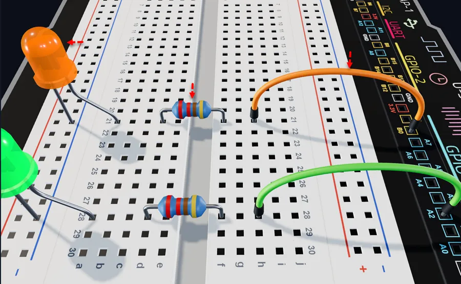
Insert an Orange LED with the short leg (–) in the bottom negative rail and the long leg (+) in pin a21, as shown.
Insert the 220 ohm resistor with one leg in d21 (next to the LED's positive leg) and the other in f21, as shown.
Connect a jumper wire from breadboard pin h21 to digital pin B0 on the UNDA.Xplora board.
Step 3
A preview of the wiring of the Blue LED on the Breadboard.
| From | Wire / Part | To | Note |
|---|---|---|---|
| Xplora Pin B14 | red | Breadboard Pin h15 | Signal Jumper Wire |
| Breadboard Pin d15 | Resistor 220 Ohms | Breadboard Pin f15 | Through-Hole Current resistor |
| Breadboard a15 | Blue LED | Breadboard Bottom GND | Connecting LED Negative to GND |
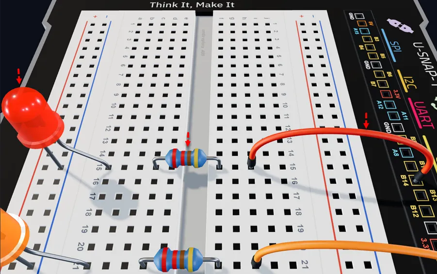
Insert the Red LED with the short leg (–) in the bottom negative rail and the long leg (+) in pin a15, as shown.
Insert the 220 ohm resistor with one leg in d15 (next to the LED's positive leg) and the other in f15, as shown.
Connect a jumper wire from breadboard pin h15 to digital pin B14 on the UNDA.Xplora board.
Step 4
A preview of the wiring of the Yellow LED on the Breadboard.
| From | Wire / Part | To | Note |
|---|---|---|---|
| Xplora Pin B7 | yellow | Breadboard Pin h9 | Signal Jumper Wire |
| Breadboard Pin d9 | Resistor 220 Ohms | Breadboard Pin f9 | Through-Hole Current resistor |
| Breadboard a9 | Yellow LED | Breadboard Bottom GND | Connecting LED Negative to GND |
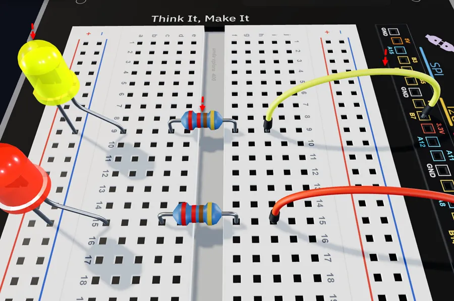
Insert the Yellow LED with the short leg (–) in the bottom negative rail and the long leg (+) in pin a9, as shown.
Insert the 220 ohm resistor with one leg in d9 (next to the LED's positive leg) and the other in f9, as shown.
Connect a jumper wire from breadboard pin h9 to digital pin B7 on the UNDA.Xplora board.
Step 5
A preview of the wiring of the Red LED on the Breadboard.
| From | Wire / Part | To | Note |
|---|---|---|---|
| Xplora Pin B3 | red | Breadboard Pin h3 | Signal Jumper Wire |
| Breadboard Pin d3 | Resistor 220 Ohms | Breadboard Pin f3 | Through-Hole Current resistor |
| Breadboard a3 | Red LED | Breadboard Bottom GND | Connecting LED Negative to GND |
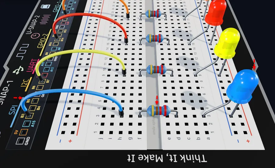
Insert an Blue LED with the short leg (–) in the bottom negative rail and the long leg (+) in pin a3, as shown.
Insert the 220 ohm resistor with one leg in d3 (next to the LED's positive leg) and the other in f3, as shown.
Connect a jumper wire from breadboard pin h3 to digital pin B3 on the UNDA.Xplora board.
Step 6
A preview of connecting the circuit to Ground (GND)
| From | Wire / Part | To | Note |
|---|---|---|---|
| Breadboard Bottom Negative Rail | black | Xplora GND Pin | Connects the entire circuit to Ground |
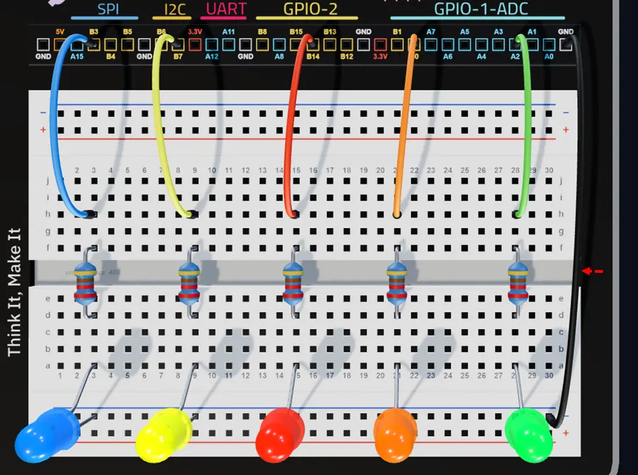
Connect one pin of the jumper from GND pin of the kit and then connect the other pin to any hole of the bottom breadboard negative rail.
Explore the project in 3D using the interactive virtual UNDA.Xplora kit:
Running Lights
Running the Project
Once you are done building the project, connect the battery to the the battery connector and then plug it to the power port of your UNDA.Xplora to power it on. Remember you can also use a USB-C Cable to power up your kit.
Once your kit is powered on, upload the Running Lights Project and open the Play Section. Try put the different options on the Play Section and observe what happens.
To learn how to upload your project refer to Xplora Menu - Projects.
Observation
Once the project has uploaded and running you will observe that the LEDs light up one after another starting with Green, Orange, Blue, yellow and Red for a period of time and the cycle repeats itself giving the running light appearance. The LEDs will flash repeatedly as long as the power is on.
If the LED does not flash, make sure you have connected the circuit correctly.
When you try out the patterns in the Play Section, you will notice that the LEDs are blinking at different patterns and times.
What makes us achieve the different patterns?
The different patterns happen because each pattern has different digital instructions sent from UNDA.Xplora.
- In Flow Pattern, the delays are very short, so the LEDs turn on and off quickly.
- In Merge, some LEDs turn on at the same time, making it look like the lights meet in the middle.
- In Bounce, the first LED blinks for a little while before the next LED starts, making the lights seem like they are bouncing across the board.
By changing the delays in the digital instruction, your Xplora Kit instructs each LED exactly when to turn on and off, creating these fun running light effects!