Introduction
We all have special things we want to keep safe, like some saved-up money, a tiny note from a friend, a favorite piece of jewelry, or a lucky stone. These little treasures deserve a special place where they can stay private and protected. That’s where a safe box comes in. A safe box gives you your own space to store your treasures and keep them safe from curious eyes or sneaky hands.
In this project, we’ll build our very own UNDA Safe Box. Our Safe Box uses a keypad to let you enter a secret security code. If you enter the correct code, the green LED lets you know that access is granted. If you enter the wrong code, the red LED lights up and the buzzer gives a short beep to let you know access is denied. But watch out! After three wrong attempts, the Safe Box goes into a 10-second lockout. The red LED flashes and the buzzer ticks while you wait before trying again. Let’s get building and make your very own UNDA Safe Box!
Build the Project
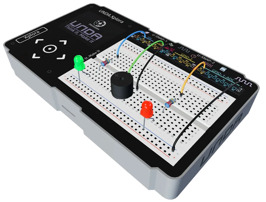
Let's build the Safe Box Project on the UNDA.Xplora breadboard.
Components Used
| # | Name | Component | Qty | Description |
|---|---|---|---|---|
| 1 | LED | 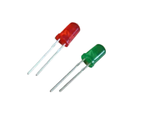 | 2 | Red and green colored LED |
| 2 | Buzzer | 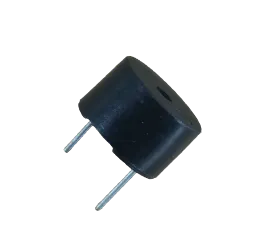 | 1 | Passive Buzzer |
| 3 | Resistor | 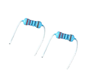 | 2 | 220 Ohm Resistor |
| 4 | Resistor | 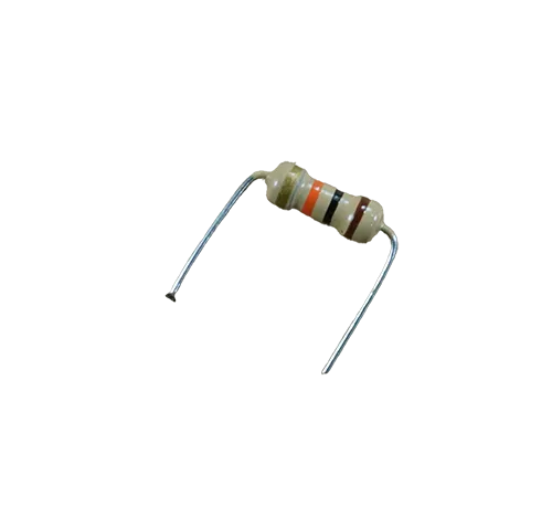 | 1 | 10 Kilo-ohm Resistor |
| 5 | Jumper Wire | 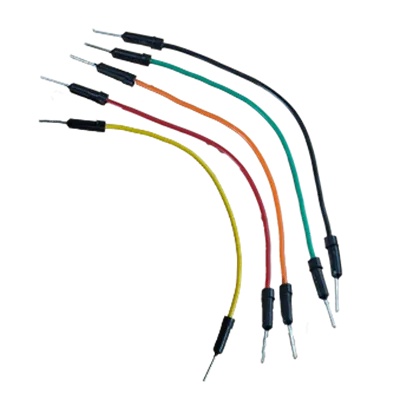 | 5 | Male-Male Jumper Wires |
| 6 | Battery Connector | 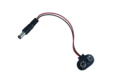 | 1 | 9V Battery Connector |
| 7 | Battery | 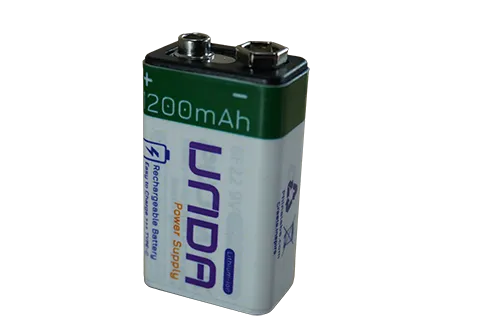 | 1 | UNDA 9V Rechargeable Battery |
| 8 | UNDA:Xplora | 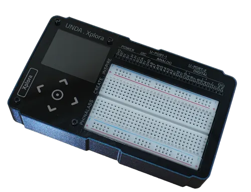 | 1 | Xplora Electronics Kit |
Step 1
A preview of how to wire the Red LED on the Breadboard.
| From | Wire / Part | To | Note |
|---|---|---|---|
| Xplora Pin B0 | yellow | Breadboard Pin h23 | Signal Jumper Wire |
| Breadboard Pin d23 | Resistor 220 Ohms | Breadboard Pin f23 | Through-Hole Current resistor |
| Breadboard a23 | Green LED | Breadboard Bottom GND | Connecting LED Negative to GND |
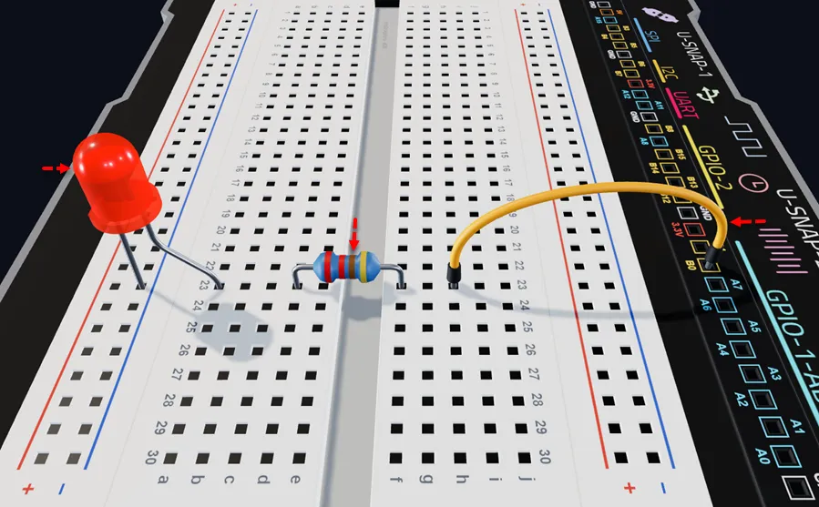
Insert a Red LED with the short leg (–) in the bottom negative rail and the long leg (+) in pin a23, as shown.
Insert the 220 ohm resistor with one leg in d23 (next to the LED's positive leg) and the other in f23, as shown.
Connect a jumper wire from breadboard pin h23 to digital pin B0 on the UNDA.Xplora board.
Step 2
Connecting the Buzzer on the Breadboard.
| From | Wire / Part | To | Note |
|---|---|---|---|
| Positive Pin | Buzzer | Breadboard Pin b12 | Connects Positive Pin of buzzer on the breadboard |
| Negative Pin | Buzzer | Breadboard Pin b15 | Connects Negative Pin of buzzer on the breadboard |
| Xplora Pin A12 | green | Breadboard Pin e12 | Signal Jumper Wire |
| Xplora GND Pin | black | Breadboard Pin e15 | Connects the negative buzzer pin to Ground (GND) |
The buzzer has positive (+) and negative (–) terminals. The positive terminal is the longer leg and is marked with a plus (+) sign, while the negative terminal is the shorter leg.
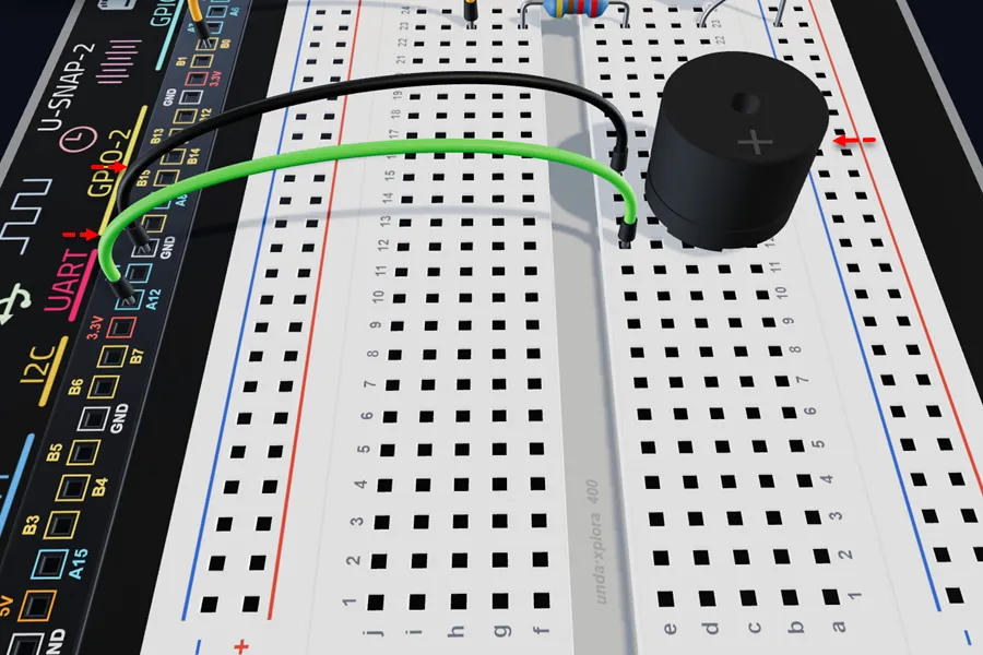
Insert the buzzer with the positive (+) leg in pin b12 and the negative (–) leg in pin b15 of the breadboard.
Connect a jumper wire from breadboard pin e12 to digital pin A12 on your kit.
Connect a jumper wire from breadboard pin e15 to any GND pin on your kit.
Step 3
A preview of how to wire the Green LED on the Breadboard.
| From | Wire / Part | To | Note |
|---|---|---|---|
| Xplora Pin B4 | blue | Breadboard Pin h4 | Signal Jumper Wire |
| Breadboard Pin d4 | Resistor 220 Ohms | Breadboard Pin f4 | Through-Hole Resistor Current resistor |
| Breadboard a4 | Green LED | Breadboard Bottom GND | Connecting LED Negative to GND |
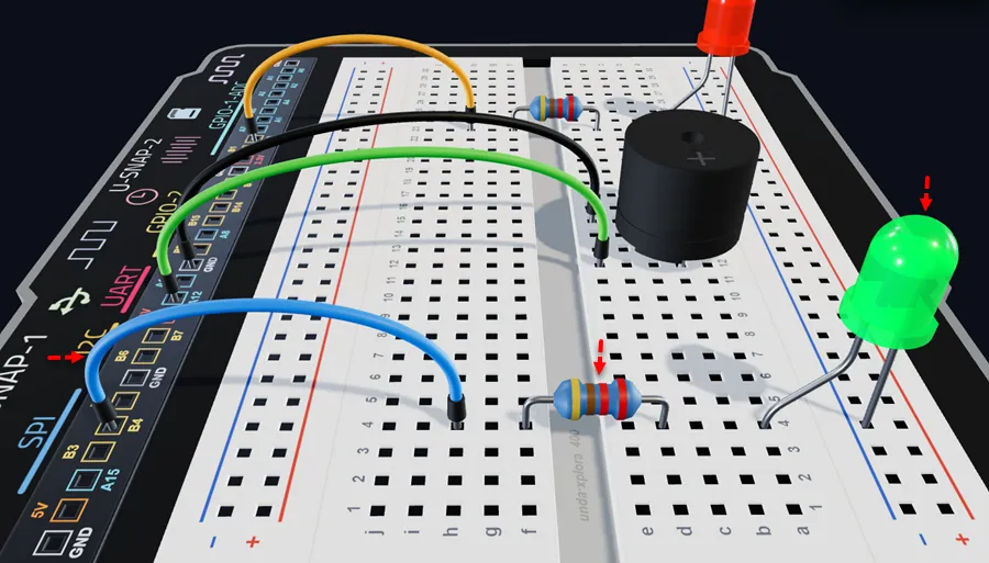
Insert a Green LED with the short leg (–) in the bottom negative rail and the long leg (+) in pin a4, as shown.
Insert the 220 ohm resistor with one leg in d4 (next to the LED's positive leg) and the other in f4, as shown.
Connect a jumper wire from breadboard pin h4 to digital pin B4 on the UNDA.Xplora board.
Step 4
Connecting Circuit to Ground(GND)
| From | Wire / Part | To | Note |
|---|---|---|---|
| Bottom Negative Breadboard Rail | black | Xplora GND Pin | Connects the circuit to Ground |
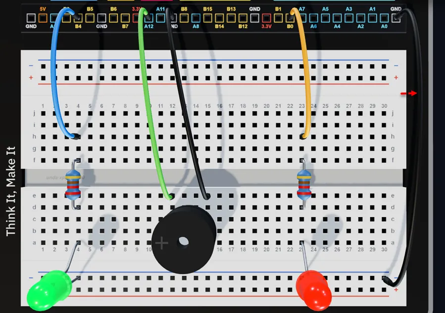
Connect one pin of the jumper from GND pin of the kit and then connect the other pin to any hole of the bottom breadboard negative rail.
Check out the virtual breadboarding for the project at:
Safe Box
Run the Project
Power up your UNDA.Xplora Kit and upload the Safe Box Project. You can refer to Xplora Menu - Projects on how to upload the project on your UNDA.Xplora.
Once fully uploaded, open Play Section and observe what happens. The observation will be different based on what time you do the project.
Correct PIN - Enter the correct security code using the keypad. The green LED turns on to indicate that access is granted, while the buzzer remains silent.
Incorrect PIN - Enter an incorrect security code. The red LED turns on and the buzzer gives a short beep to indicate that access is denied.
Three Wrong Attempts - After three consecutive incorrect attempts, the system enters a 10-second lockout. The red LED flashes and the buzzer ticks during the countdown. Once the countdown ends, you can try entering the PIN again.
Observation
Correct PIN - Enter the correct security code using the keypad. The green LED turns on to show that access is granted, and the buzzer remains silent.
Incorrect PIN - Enter an incorrect security code. The red LED turns on and the buzzer gives a short beep to show that access is denied.
Three Wrong Attempts - After three consecutive incorrect attempts, the system enters a 10-second lockout. The red LED flashes and the buzzer ticks during the countdown. After 10 seconds, you can try entering the PIN again.