Introduction
Wee-woo, wee-woo! Have you ever heard that loud “wee-woo” sound when you’re walking on the road or riding in a car? That’s a siren, and it means something very important is happening!
When a police car sees someone breaking the law, it turns on its siren and flashing lights to say, “Hey everyone, please move aside!”
An ambulance uses its siren to rush to people who are hurt or very sick. Its “wee-woo” tells us, “Make way someone needs help right now!”
Fire trucks drive quickly to put out fires or help people in danger. Their siren warns us, “Alert! Firefighters are coming to save the day!”
And that’s why they are super loud, so everyone can hear them from far away, even with traffic, music, and busy streets.
Now that you know what a siren does, are you ready to build one yourself?
Build the Project
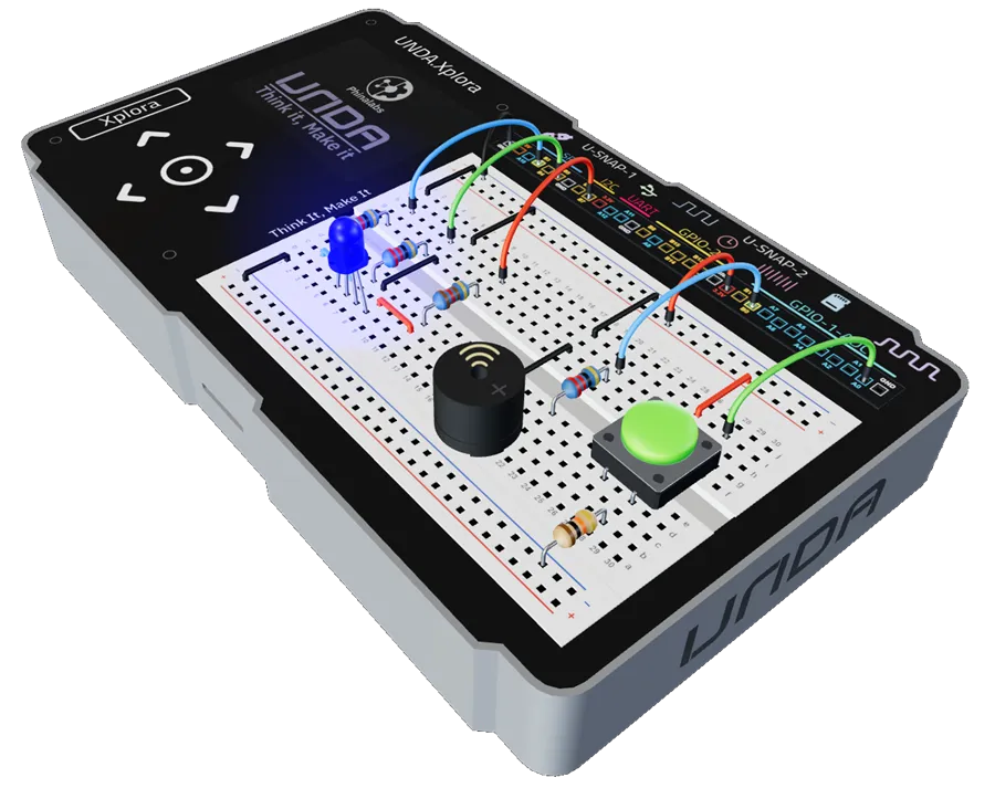
In this section, we will build the Siren Project on our UNDA.Xplora breadboard. Before building, ensure you have the following components.
Components Used
| # | Name | Component | Qty | Description |
|---|---|---|---|---|
| 1 | RGB | 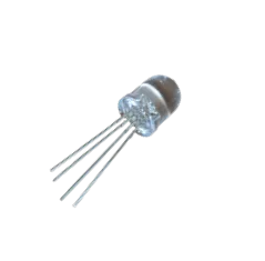 | 1 | Common Cathode RGB LED |
| 2 | Push Button | 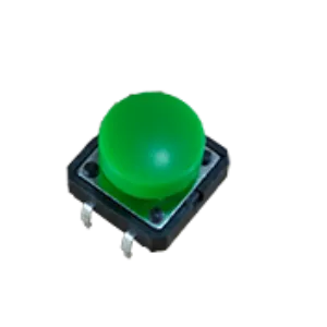 | 1 | Choose your preferred button color |
| 3 | Buzzer | 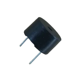 | 1 | Passive Buzzer |
| 4 | Resistor 1 | 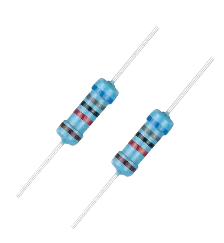 | 2 | 68 Ohm Resistor for the Green and Blue Pin of the RGB. |
| 5 | Resistor 2 | 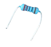 | 1 | 220 ohm resistor for the Red Pin of the RGB. |
| 6 | Resistor 3 | 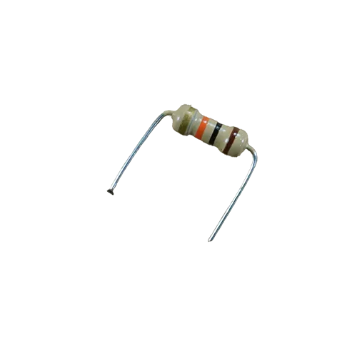 | 1 | 10 Kilo-ohm Resistor for the push button. |
| 7 | Jumper Wire | 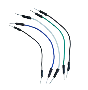 | 4 | Male-Male Jumper Wires |
| 8 | Breadboarding Wires | 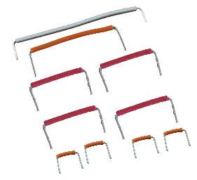 | 10 | Choose suitable sized breadboarding wire for the connections |
| 9 | Battery Connector | 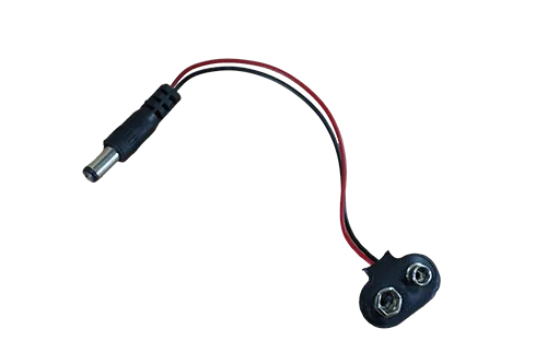 | 1 | 9V Battery Connector |
| 10 | Battery | 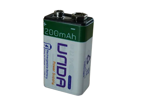 | 1 | UNDA 9V Rechargeable Battery |
| 11 | UNDA:Xplora | 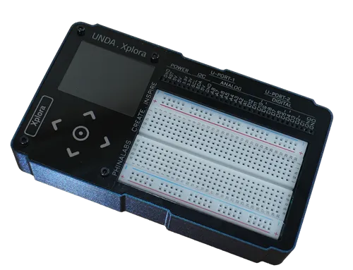 | 1 | Xplora Electronics Kit |
Step 1
Connecting to the Top Positive and Negative Power Rails
| From | Wire / Part | To | Note |
|---|---|---|---|
| Xplora 3.3V Pin | red | Top Positive Breadboard Rail | 3.3V power supplied to all pins of the top positive rail |
| Xplora GND Pin | black | Top Negative Breadboard Rail | GND Connection supplied to all pins of the top positive rail |
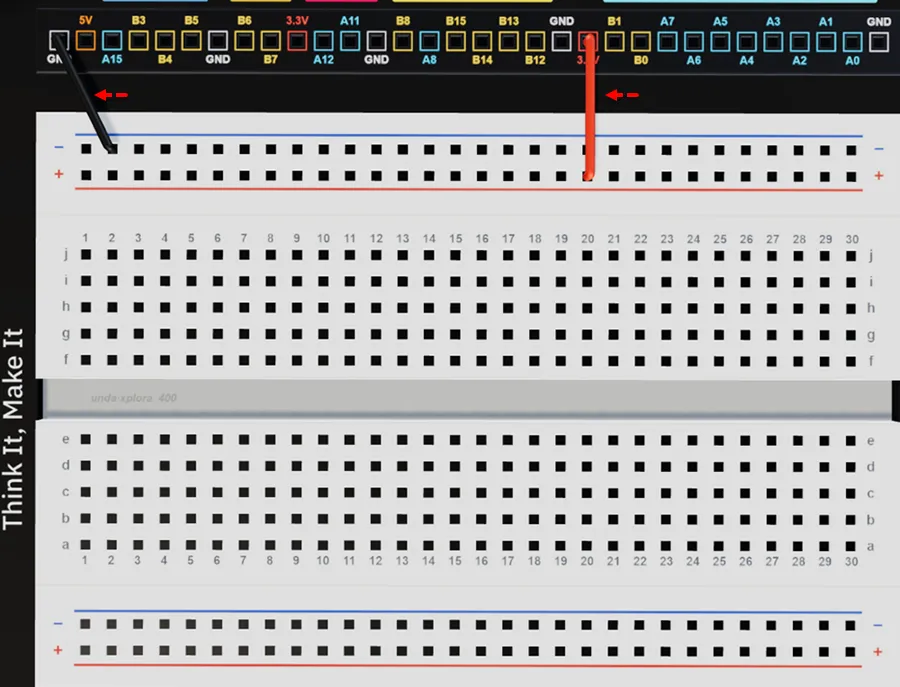
Connect a breadboarding jumper wire from the 3.3V pin on your kit to the top positive breadboard rail.
Connect a breadboarding jumper wire from the GND pin on your kit to the top negative breadboard rail.
Step 2
Connecting the push button on the breadboard.
| From | Wire / Part | To | Note |
|---|---|---|---|
| Push button | Push button | Breadboard Pins (top-26 & g28) (bottom-d26 & d28) | Connecting Pushbutton 2 on the Breadboard |
| Breadboard pin b28 | Resistor 10Kilo-ohm | Bottom Breadboard Rail | Pull-down resistor for button 1 |
| Xplora Pin A0 | green | Breadboard Pin i28 | Signal Jumper Wire for push button |
| Top Positive Breadboard Rail | red | Breadboard Pin i26 | Supplies 3.3V power to the button |
| Bottom Negative Breadboard Rail | black | Top Negative Breadboard Rail | Connects the push button to GND Connection |
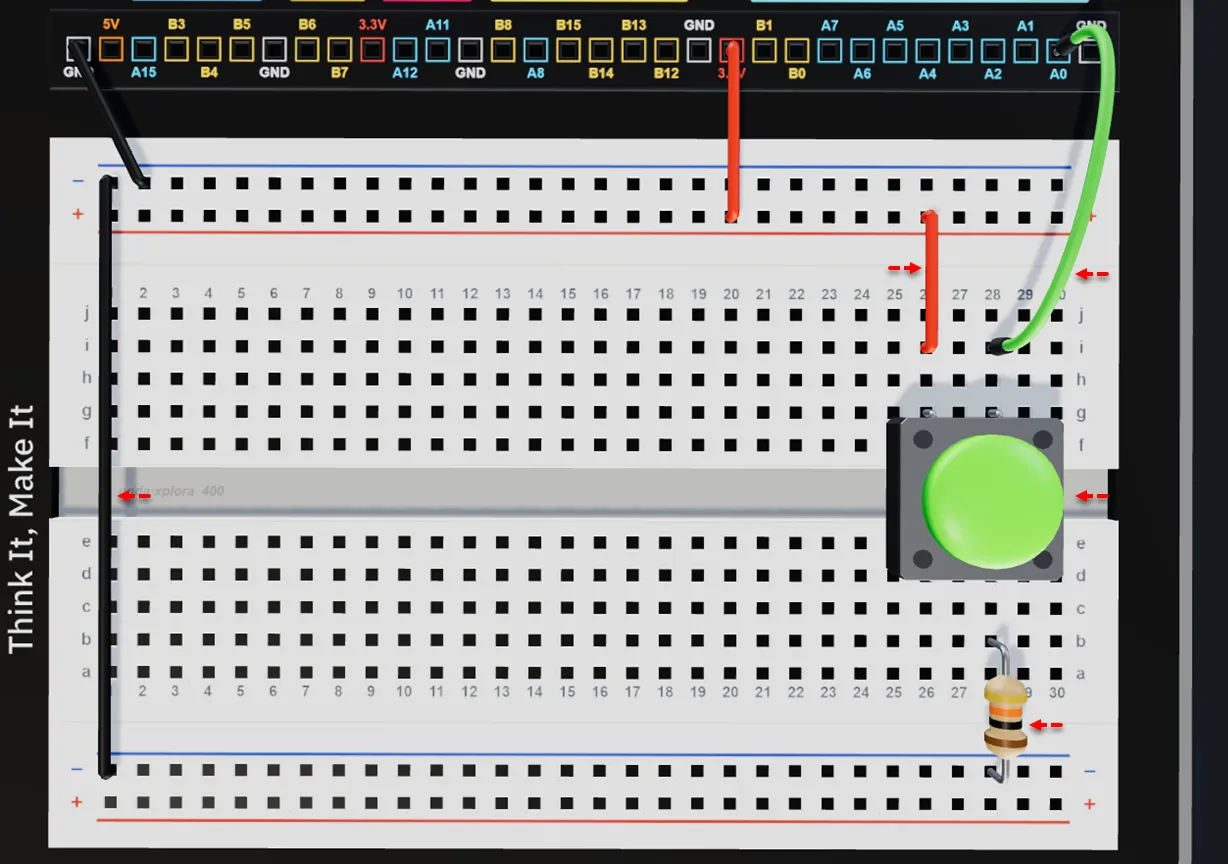
Place the pushbutton with its top pins breadboard pins g26 and g28, and its bottom pins in g26 and g28.
Insert a 10 kΩ resistor with one leg in b28 and the other in any pin of the bottom negative breadboard rail.
Connect a jumper wire from breadboard pin i28 to digital pin A0 on the UNDA.Xplora board.
Connect a breadboarding jumper wire from the top positive breadboard rail to breadboard pin i26.
Connect a breadboarding jumper wire from the top negative breadboard rail to bottom negative breadboard rail.
Step 3
Connecting the Buzzer on the Breadboard.
| From | Wire / Part | To | Note |
|---|---|---|---|
| Buzzer Positive Pin | Buzzer | Breadboard Pin a21 | Connects Positive Pin of buzzer on the breadboard |
| Buzzer Negative Pin | Buzzer | Breadboard Pin a18 | Connects Negative Pin of buzzer on the breadboard |
| Breadboard Pin g21 | Resistor 68 ohms | Breadboard Pin e21 | Limits current that gets to the buzzer |
| Xplora Pin B14 | blue | Breadboard Pin h21 | Signal Jumper Wire |
| Top Negative Rail | black | Breadboard Pin i18 | Connect GND to the column 14 |
| Breadboard Pin g18 | black | Breadboard Pin e18 | Connects the negative buzzer pin to Ground (GND) |
The positive leg of the buzzer is the longer leg and is marked with a plus (+) sign, while the negative leg is the shorter leg.
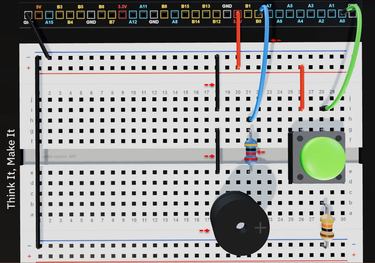
Insert the buzzer with the positive (+) leg in pin a21 and the negative (–) leg in pin a18 of the breadboard.
Insert the 68 ohm resistor with one leg in e21 (next to the buzzer's positive leg) and the other in g21, as shown.
Connect a jumper wire from breadboard pin h21 to digital pin B14 on your kit.
Connect a breadboarding jumper wire from the top negative breadboard rail to breadboard pin i18.
Connect a jumper wire from breadboard pins g18 to e18 to connect the buzzer to GND.
Step 4
Placing RGB LED on the breadboard.
| From | Wire / Part | To |
|---|---|---|
| Breadboard Pin c8 | red | Breadboard Pin c11 |
| Breadboard Pin c5 | blue | Breadboard Pin c2 |
| RGB PINS | LED RGB | Breadboard pin b8,b7,b6 and b5 |
Ensure the RGB LED is inserted in the correct orientation. The Negative pin (longest pin) should be in b7, the Red pin in b8, the Green pin in b6, and the Blue pin in b5.
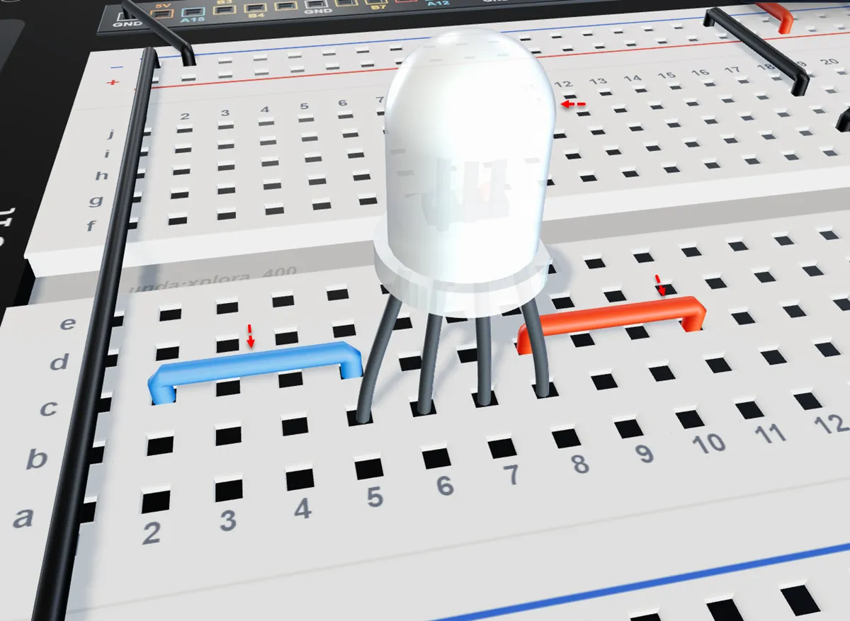
Insert a Breadboarding Wire from breadboard pin c8 to breadboard pin c11, connecting breadboard columns 8 and 13.
Insert another Breadboarding Wire from breadboard pin c5 to breadboard pin c2, connecting column 5 and column 2.
Insert the RGB LED into the breadboard with Pin 1 in b8, the Negative Pin in b7, Pin 3 in b6, and Pin 4 in b5.
Step 5
Wiring the Negative Pin of the RGB LED.
| From | Wire / Part | To | Note |
|---|---|---|---|
| Top Negative Breadboard Rail | black | Breadboard Pin i7 | RGB LED Ground Conenction |
| Breadboard Pin f7 | black | Breadboard Pin d7 | Extends the GND Connection to the negative leg of the RGB |
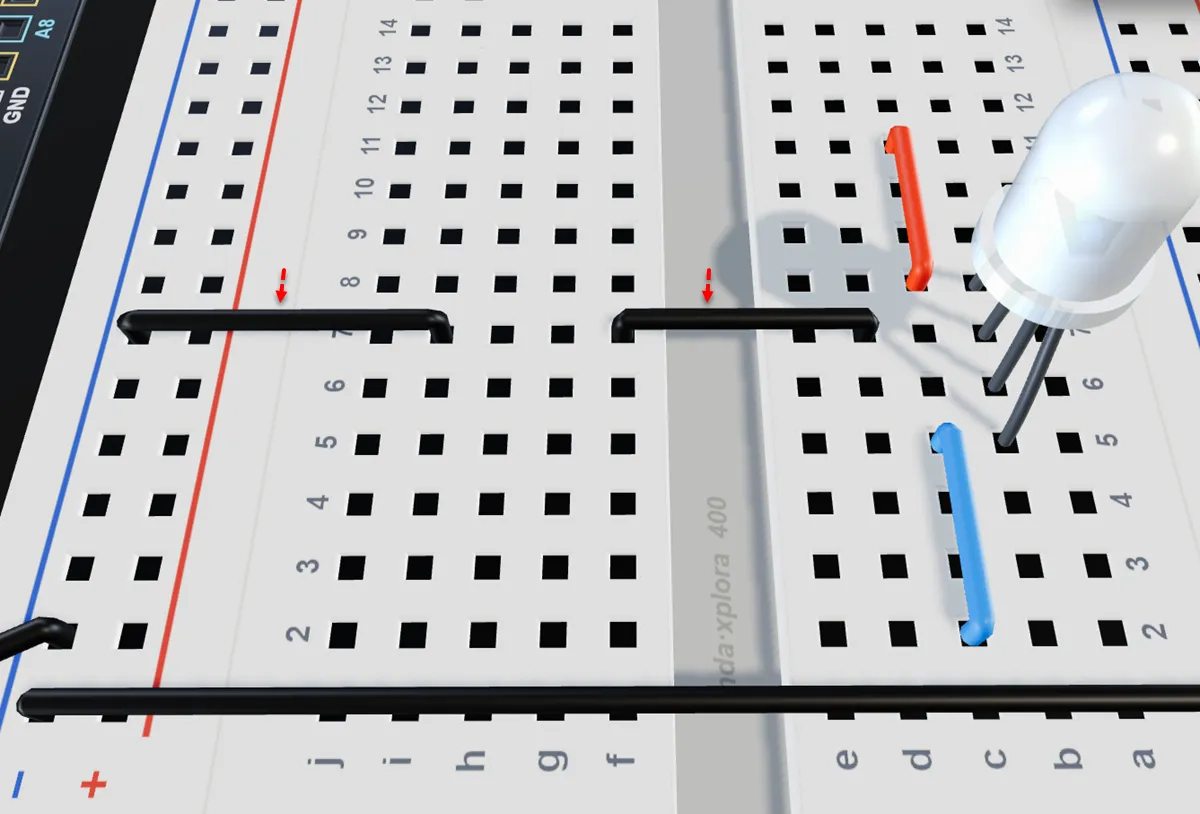
Connect a breadboarding jumper wire from the top negative breadboard rail to breadboard pin i7.
Connect a jumper wire from f7 to d7 to connect the `RGB LED' Negative Leg to GND.
Step 6
Placing a current-limiting Resistor next to each RGB Pin.
| From | Wire / Part | To | Note |
|---|---|---|---|
| Breadboard pin d2 | Resistor 68 0hms | Breadboard pin f2 | Resistor for the Blue Pin of the RGB LED |
| Breadboard pin d6 | Resistor 68 0hms | Breadboard pin f6 | Resistor for the Green Pin of the RGB LED |
| Breadboard pin d11 | Resistor 220 0hms | Breadboard pin f11 | Resistor for the Red Pin of the RGB LED |
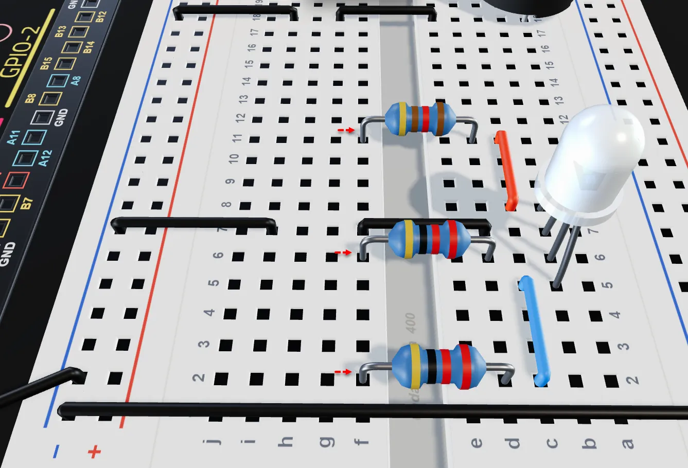
Insert a 68-ohm resistor between Breadboard Pin d2 and Breadboard Pin f2.
Insert the 68-ohm resistor with one leg in pin d6 and the other leg in pin f6 of the breadboard.
Insert the 220-ohm resistor with one leg in pin d11 and the other leg in pin f11 of the breadboard.
Step 7
Connecting the RGB LED pins to Xplora digital pins.
| From | Wire / Part | To | Note |
|---|---|---|---|
| Xplora PWM Pin B3 | blue | Breadboard pin h2 | Breadboard pin i18 |
| Xplora PWM Pin B5 | green | Breadboard pin h6 | Signal Jumper Wire |
| Xplora PWM Pin B7 | red | Breadboard pin h11 | Signal Jumper Wire |
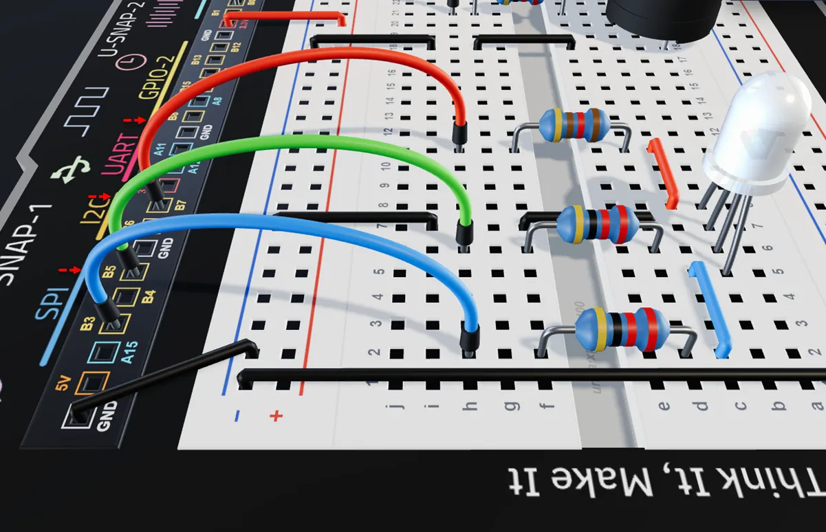
Connect a jumper wire from h2 on the breadboard to PWM pin B3 on the UNDA Xplora board.
Connect a jumper wire from h6 on the breadboard to PWM pin B5 on the UNDA Xplora board.
Connect a jumper wire from h11 on the breadboard to PWM pin B7 on the UNDA Xplora board.
Explore the virtual version of this project in the Xplora 3D app:
Siren
Run the Project
Once you are done building the project, power up your kit. Once it powers up, navigate t the Project Menu and them select the Siren Project and upload it. The Play Section Section open automatically and press the push button and observe what happens.
You can refer to Xplora Menu - Projects to check out the steps of how to upload the project.
Observation
When the pushbutton is pressed, the buzzer turns on and the RGB LED flashes, creating a siren-like effect with both sound and light; pressing the button again turns both the buzzer and LED off.