Introduction
What’s the weather like today? Is it sunny outside, or are there clouds in the sky? Does the air feel hot, or is it cool?
The weather changes every day. It helps us decide what clothes to wear, what games we can play outside, and even affects how plants and animals behave.
Sometimes we try to guess the weather by looking at the sky or feeling the air with our hands. But wouldn’t it be more fun to build something that can measure it for real?
In this project, you’ll build a weather station that helps you observe and record the weather around you
This mini weather station uses a light sensor to tell how bright or dark it is. This helps you know if it’s sunny, cloudy, or getting close to sunset and temperature sensor to measure how hot or cold the air is.
With these sensors, you’ll be able to track how the weather changes during the day, compare morning and afternoon temperatures, and even see how indoor and outdoor weather feels different.
So no more weather guessing. Now you can read the weather like a meteorologist, using real tools and sensors to measure, track, and understand what’s happening in the world around you.
Let’s start building
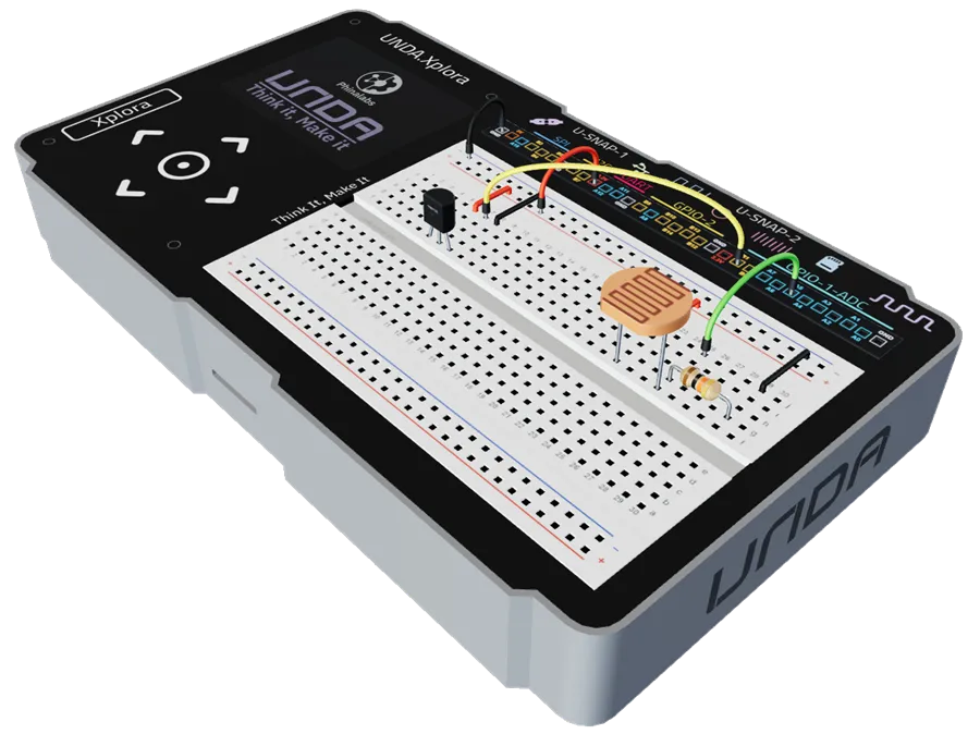
Build the Project
In this section we will explore how to use UNDA.Xplora to build the mini Weather Station.
Components Used
| # | Name | Component | Qty | Description |
|---|---|---|---|---|
| 1 | Light Sensor (LDR) | 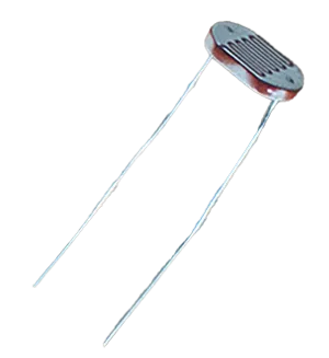 | 1 | Senses the ambient light intensity |
| 2 | Temperature Sensor | 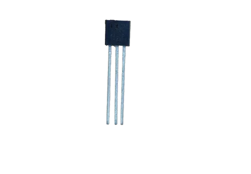 | 1 | TMP 36 with operating range between -40°C to +125°C |
| 3 | Resistor | 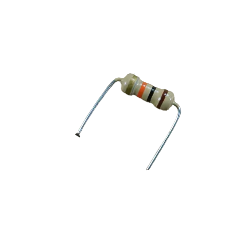 | 1 | 10 Kilo-ohm Resistor |
| 4 | Jumper Wire | 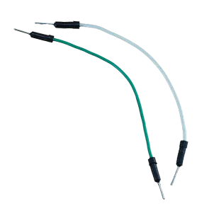 | 2 | Male-Male Jumper Wires |
| 5 | Breadboarding Jumper Wires | 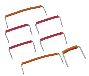 | 6 | Choose breadboarding wires that fit easily between connection points |
| 6 | Battery Connector | 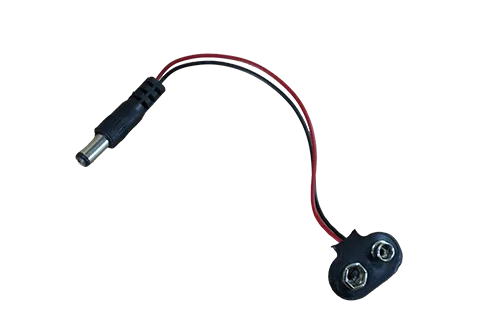 | 1 | 9V Battery Connector |
| 7 | Battery | 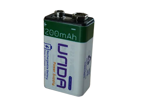 | 1 | UNDA 9V Rechargeable Battery |
| 8 | UNDA:Xplora | 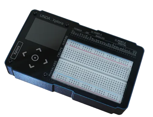 | 1 | Xplora Electronics Kit |
Step 1
| From | Wire / Part | To | Note |
|---|---|---|---|
| Pin 1 | Temperature Sensor | Breadboard Pin f6 | Positive pin of sensor connected on the breadboard |
| Pin 2 | Temperature Sensor | Breadboard Pin f7 | Signal pin of sensor connected on the breadboard |
| Pin 3 | Temperature Sensor | Breadboard Pin f8 | Negative pin of sensor connected on the breadboard |
Before inserting the TMP36, ensure the flat side faces you. This places Pin 1 (+) on the left, Pin 2 (Signal) in the middle, and Pin 3 (–) on the right.
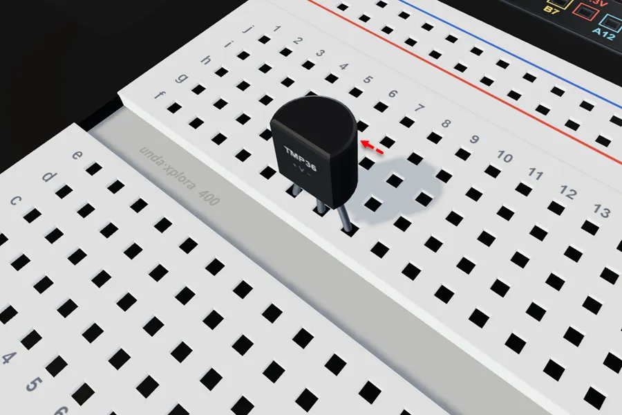
Place the TMP36 with Pin 1 (+) in f6, Pin 2 (Signal) in f7, and Pin 3 (–) in f8.
Step 2
Connecting the Light Sensor on the breadboard.
| From | Wire / Part | To | Note |
|---|---|---|---|
| LDR Pin 1 | LDR | Breadboard Pin f22 | Placing Pin 1 on the breadboard |
| LDR Pin 2 | LDR | Breadboard Pin f25 | Placing Pin 2 on the breadboard |
| Breadboard Pin g25 | Resistor 10 Kilo-Ohm | Breadboard Pin g29 |
The light sensor has two legs and it also has no polarity which means it has no positive and negative terminal Pins and therefore you can connect it in any orientation.
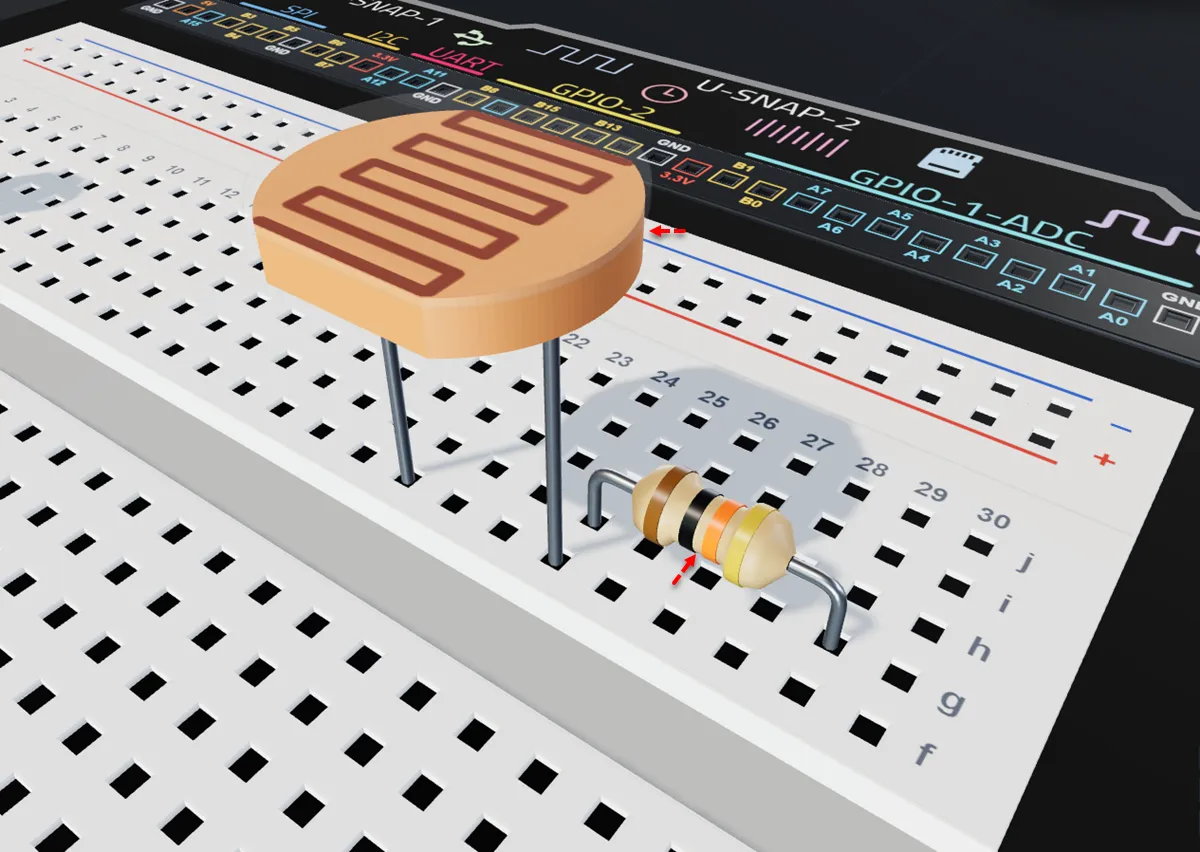
Insert the light sensor with one leg in breadboard pin f22 and the other in pin f25.
Insert a 10 kΩ resistor with one leg in breadboard pin g25 and the other leg into breadboard pin g29.
Step 3
Connecting the Sensors to 3.3 Power.
| From | Wire / Part | To | Note |
|---|---|---|---|
| Xplora 3.3V Pin | red | Top Positive Breadboard Rail | 3.3V Power supplied to top positive breadboard rail |
| Top Positive Breadboard Rail | orange | Breadboard Pin j6 | Supplies 3.3V power to the temperature sensor |
| Top Positive Breadboard Rail | orange | Breadboard Pin j22 | Supplies 3.3V power to the light sensor |
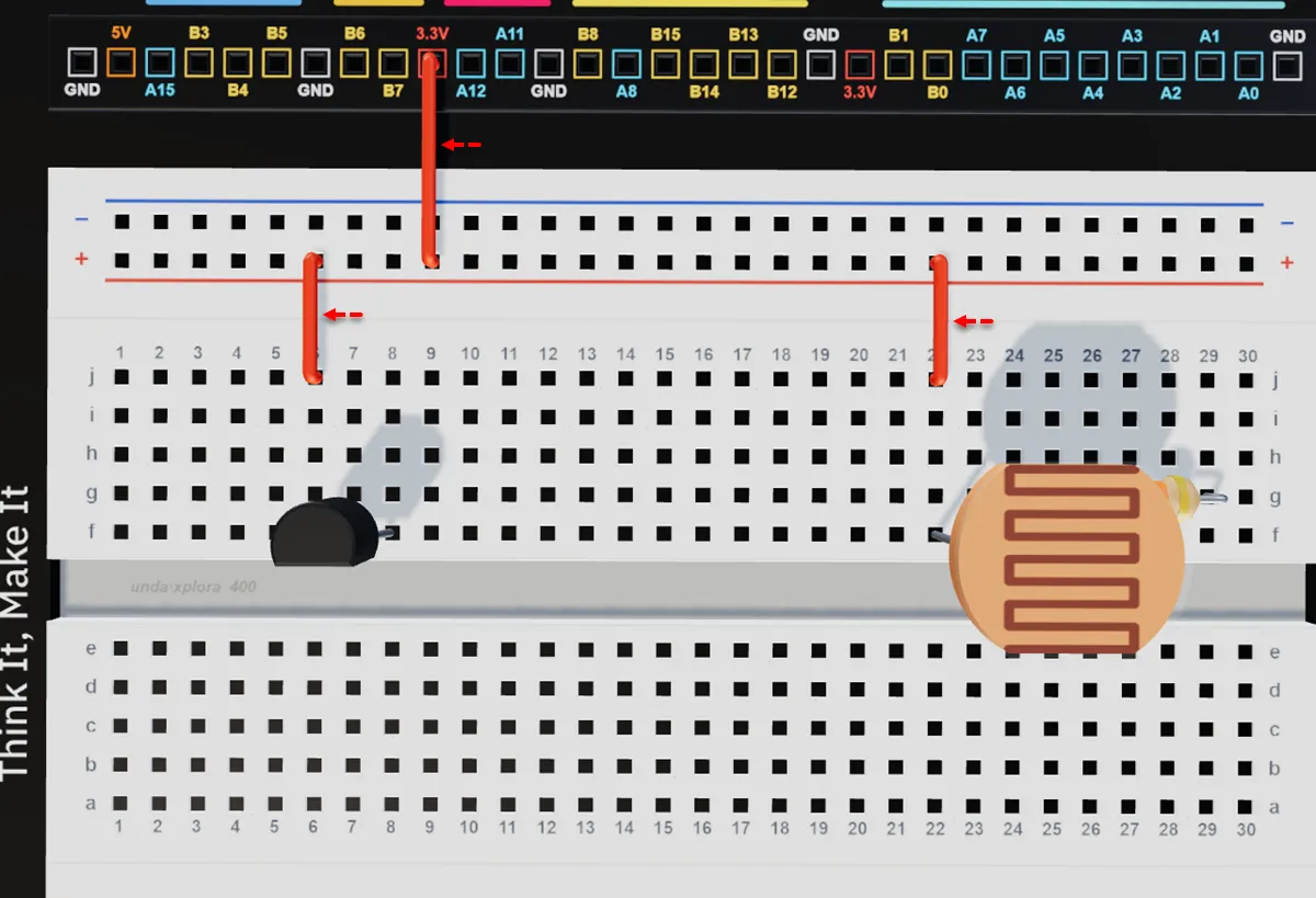
Connect a breadboarding jumper wire from any 3.3V pin on your kit to the top positive breadboard rail.
Connect a breadboarding jumper wire from the top positive breadboard rail to breadboard pin j6, next to the positive pin of the TMP36 sensor.
Connect a breadboarding jumper wire from the top positive breadboard rail to breadboard pin j22, next to the pin 1 of the LDR.
Step 4
Connecting the circuit to Ground (GND).
| From | Wire / Part | To | Note |
|---|---|---|---|
| Bottom Negative Breadboard Rail | black | Xplora GND Pin | Connects bottom negative rail to Ground (GND) Connection |
| Breadboard Pin j8 | black | Top Negative Breadboard Rail | Connects the Temperature Sensor to GND Connection |
| Breadboard Pin j29 | black | Top Negative Breadboard Rail | Connects the Light Sensor to GND Connection |
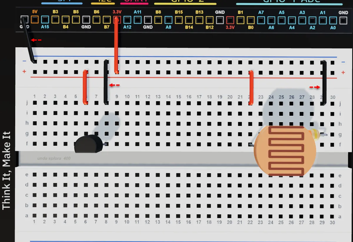
Connect a jumper wire from any GND pin on your kit to any pin of the top negative breadboard rail.
Run a breadboarding jumper wire from the top negative breadboard rail to breadboard pin j8, (next to the negative pin of the tmp36).
Run a breadboarding jumper wire from the top negative breadboard rail to breadboard pin e29.
Step 5
Connecting the sensors to Xplora digital pins.
| From | Wire / Part | To | Note |
|---|---|---|---|
| Xplora Pin A5 | green | Breadboard Pin j25 | Signal Jumper Wire for the light sensor |
| Xplora Pin B1 | blue | Breadboard Pin j7 | Signal Jumper Wire for the temperature sensor |
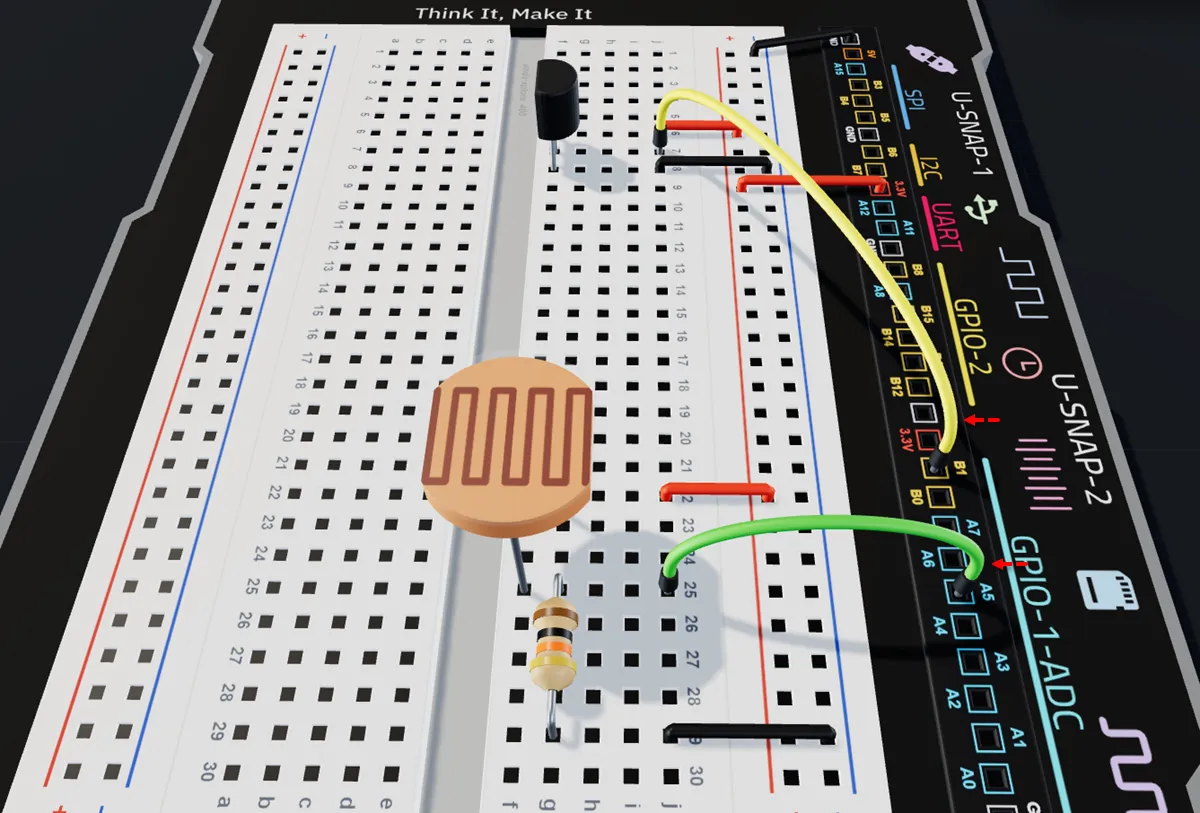
Connect a jumper wire from breadboard pin j25 to ADC pin A5 on the UNDA.Xplora board.
Connect a jumper wire from breadboard pin j7 (next to the signal pin of the sensor) to ADC pin B1 on the UNDA.Xplora board.
Check out the virtual breadboarding for the same project at:
Weather Station
Run the Project
After you are done building the project, connect the battery to the battery connector and then plug it to the power port of your UNDA.Xplora to power it on.
Once it powers on, upload the Weather Station Project and Play Section automatically opens once it is fully loaded. Press the temperature sensor gently but firmly or you can also blow on it and check changes in Play section.
Also check the reading for light levels and cover it if project is done at day time or shine light on it if project is done at night.
Refer to Xplora Menu - Projects on how to load the project on your UNDA.Xplora.
Observation
When you press the temperature sensor gently but firmly, or blow on it, the temperature reading in the Play Section changes, showing how the sensor responds to heat from your body or breath.
At the same time, the light level reading also changes—if you cover the LDR during the day, the value decreases, and if you shine light on it at night, the value increases. This shows how both sensors detect and respond to changes in their environment.