Introduction
When you walk or drive on a road at night, you’ll see glowing lamps lighting up the road. Those are street lights, and they help us see clearly when it’s dark.
Street lights turn on when it’s dark outside and turn off when it’s bright again. They don’t need someone to flip a switch….they have a special sensor that can tell if it’s day or night. When the sun goes down, the light comes on automatically.
This helps save energy and keeps the roads bright only when needed.
Street lights are very important in cities, towns, and even small roads. They help drivers see the road clearly so they don’t bump into anything. They also help people who are walking or riding bikes stay safe at night. And they make people feel safer when they’re outside after dark.
In this project, you will build your own mini street light using a light sensor. You’ll be able to see how the sensor can tell when it’s dark and turn the light on.
Build the Project
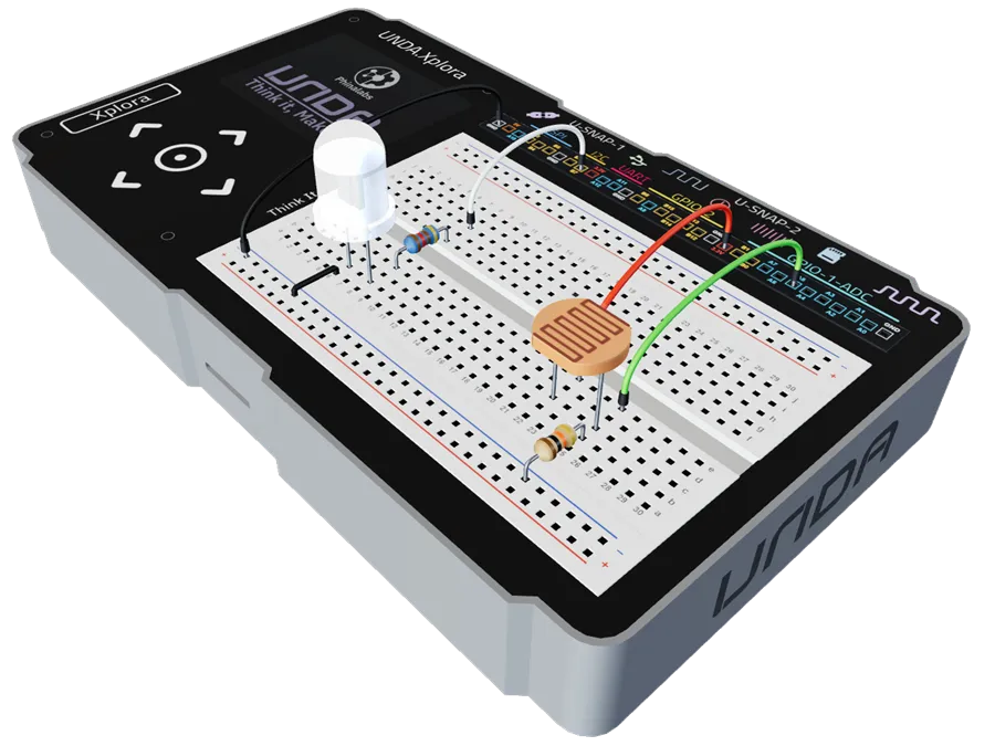
In this section we will explore how to use UNDA.Xplora to build a simple automatic street light.
Components Used
| # | Name | Component | Qty | Description |
|---|---|---|---|---|
| 1 | Light Sensor | 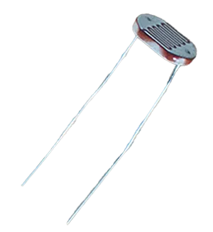 | 1 | Senses the ambient light intensity |
| 2 | LED | 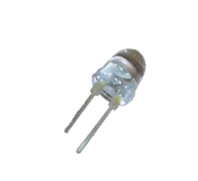 | 1 | White colored LED |
| 3 | Resistor | 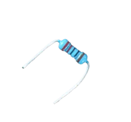 | 1 | 220 Ohm Resistor |
| 4 | Resistor | 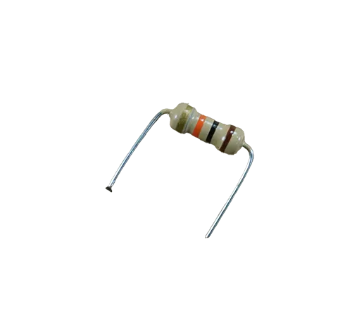 | 1 | 10 Kilo-ohm Resistor |
| 5 | Jumper Wire | 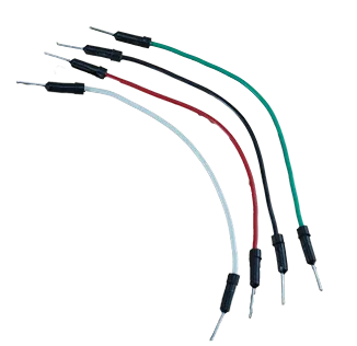 | 4 | Male-Male Jumper Wires |
| 6 | Breadboarding Wire | 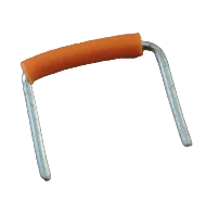 | 1 | Small-sized breadboarding wire |
| 7 | Battery Connector | 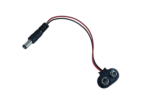 | 1 | 9V Battery Connector |
| 8 | Battery | 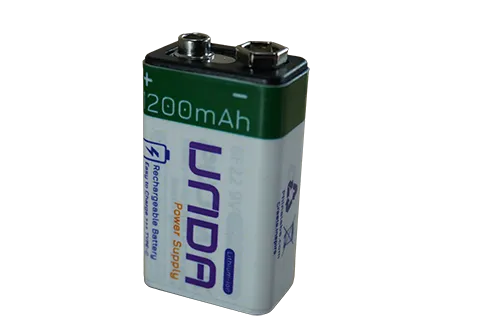 | 1 | UNDA 9V Rechargeable Battery |
| 9 | UNDA:Xplora | 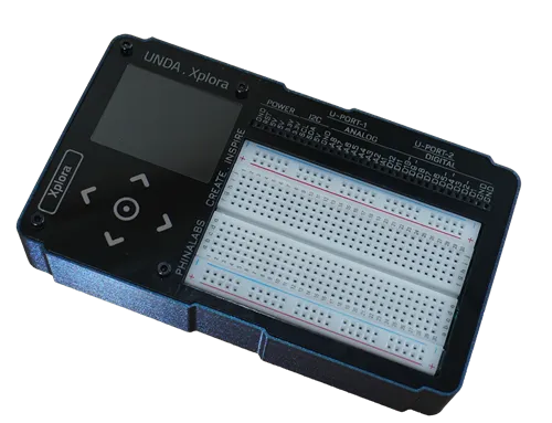 | 1 | Xplora Electronics Kit |
Step 1
Wiring the White LED on the breadboard.
| From | Wire / Part | To | Note |
|---|---|---|---|
| Xplora B7 | white | Breadboard Pin h8 | Signal Jumper Wire |
| Breadboard Pin d8 | Resistor 220 Ohms | Breadboard Pin f8 | Through-Hole Current resistor |
| Breadboard Pin b8 | White LED | Breadboard Pin b6 | Connecting the LED on the Breadboard. |
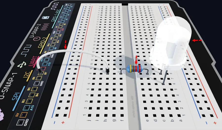
Insert a White LED with the short leg (–) into pin b6 and the long leg (+) in pin b8 of the breadboard.
Insert the 220 ohm resistor with one leg in d8 (next to the LED's positive leg) and the other in f8, as shown.
Connect a jumper wire from breadboard pin h8 to digital pin B7 on the UNDA.Xplora board.
Always double-check that the LED is inserted with the correct positive (+) and negative (–) legs. Swapping the legs may damage or burn out the LED.
Step 2
Connecting the Light Sensor on the breadboard.
| From | Wire / Part | To | Note |
|---|---|---|---|
| LDR Pin 1 | LDR | Breadboard Pin c22 | Placing Pin 1 on the breadboard |
| LDR Pin 2 | LDR | Breadboard Pin c25 | Placing Pin 2 on the breadboard |
| Breadboard Pin b25 | Resistor 10 Kilo-Ohm | Bottom Negative Breadboard Rail | Forms voltage divider with the light sensor |
The light sensor has two legs and it also has no polarity which means it has no positive and negative terminal Pins and therefore you can connect it in any orientation.
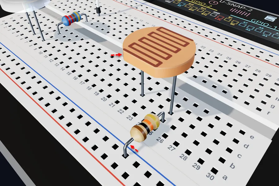
Insert the light sensor with one leg in breadboard pin c22 and the other in pin c25.
Insert a 10 kΩ resistor with one leg in breadboard pin b25 and the other in any pin of the bottom negative breadboard rail.
The 10 kΩ resistor and the light sensor (LDR) form a voltage divider so as to to create a changing voltage that the ADC pin can measure.
To learn more about how the light sensor works, see the Light Sensor Tutorial.
Step 3
Wiring the Light Sensor
| From | Wire / Part | To | Note |
|---|---|---|---|
| Xplora Pin A5 | green | Breadboard Pin e25 | Signal Jumper Wire |
| Xplora 3.3V Pin | red | Breadboard Pin e22 | Connects the sensor to 3.3V Power |
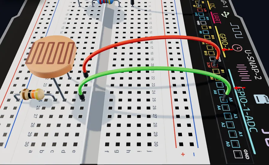
Connect a jumper wire from ADC Pin A5 on your kit to breadboard pin e25.
Connect a jumper wire from any 3.3V pin of the UNDA.Xplora board to breadboard pin e22.
Step 4
Connecting Circuit to Ground(GND)
| From | Wire / Part | To | Note |
|---|---|---|---|
| Bottom Negative Breadboard Rail | black | Xplora GND Pin | Connects bottom negative rail to Ground (GND) Connection |
| Breadboard Pin a6 | black | Bottom Negative Breadboard Rail | Connects the LED to Ground Connection |
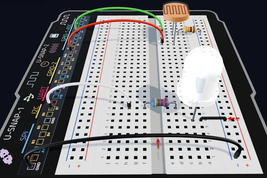
Connect a jumper wire from any GND pin on your kit to any pin of the bottom negative breadboard rail.
Run a breadboarding jumper wire from the bottom negative breadboard rail to breadboard pin a23.
Check out the 3D View Simulation for the project at:
Street Light
Run the Project
Power your UNDA.Xplora using either the battery or the USB-C Cable. Once it is turned on, upload the project from the Projects Menu and once fully loaded open the Play Section. Once uploaded:
If you are doing the project during day time, cover the LDR to mimic (darkness) and if you are doing it at night use a flashlight and shine the light on the LDR.
Refer to Xplora Menu - Projects on how to load the project on your UNDA.Xplora
Observation
This project utilizes a Light Sensor to control an LED based on light levels. Once the project has been loaded, the first observation will be dependent on the current light level and thus you can expect either of the observations:
Day-time Behavior: When the project is powered on during the day, there is bright light and thus LED remains off because the light sensor detects high levels of light. In order to turn the LED on, cover the light sensor with your finger to block the light.
Night-time Behavior: Powering the project at night or in low-light conditions, the LED turns on automatically as the light sensor detects limited or no light. If you want to turn the LED off, shine a torch or any light source onto the sensor to increase the light level.