Introduction
An LDR, also called a photoresistor, is a type of resistor that changes its resistance depending on the amount of light falling on it and thus can be used as a light sensor. It is used to detect whether the environment is bright or dark.
3D Model View
LDR
Click to load 3D model
Applications
LDRs are being used in the following areas:
Automatic Light Systems – Turns lights ON at night and OFF during the day.
Light-Sensing Alarms – Detects sudden changes in light e.g., door opened.
Screen Brightness Control – Adjusts device screen brightness automatically.
Smart Lighting Systems – Adjusts brightness based on surrounding light.
How the LDR Works
An ldr works using the voltage divider principle. However, before we dive deeper into how it works, let us look at what the ldr is made up of.
Parts of an LDR
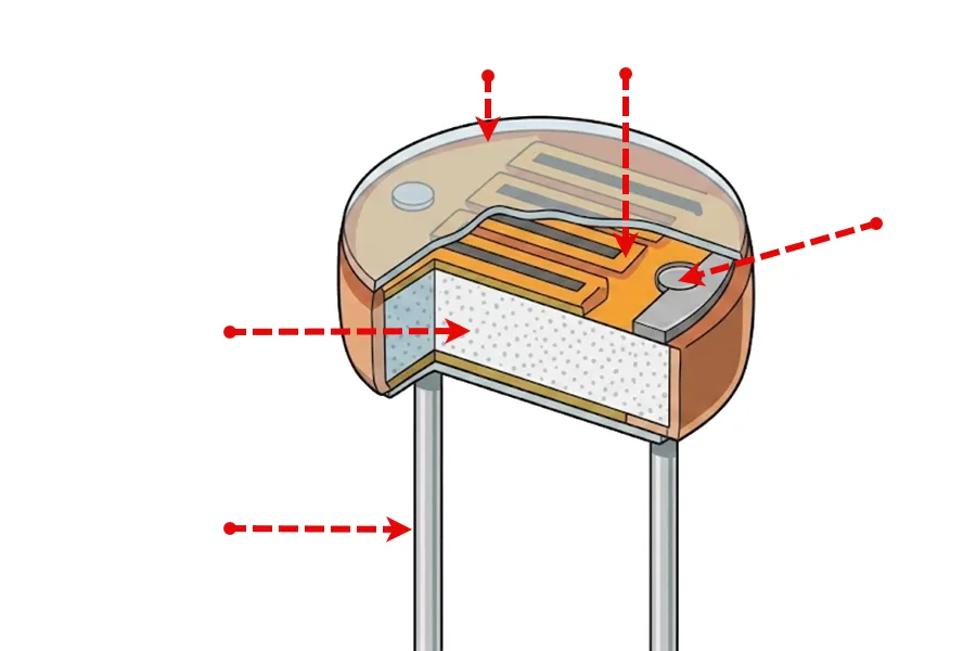
Protects the LDR from damage while allowing light to pass through to the sensor.
Semiconductor material and when light hits this layer, its resistance changes with light.
Metal contacts that collect and transfer current through the LDR and they also c0nnect to LDR leads.
Provides support and structure for the LDR and holds the layers in place.
The are metal pins that are used to connect the LDR on the breadboard.
LDR Polarity
Unlike LEDs and buzzers, LDRs are non-polarized components. This means they have no positive or negative terminals and can be connected in either direction in a circuit.
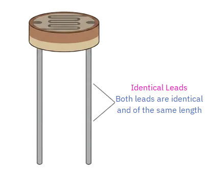
Both leads of an LDR are identical and are of the same length. This makes LDRs easier to work with compared to polarized components.
How it Works
An LDR changes its resistance depending on amount of light it receives. This change in resistance is applied in voltage divider to produce varying output voltage.
Voltage Divider Setup
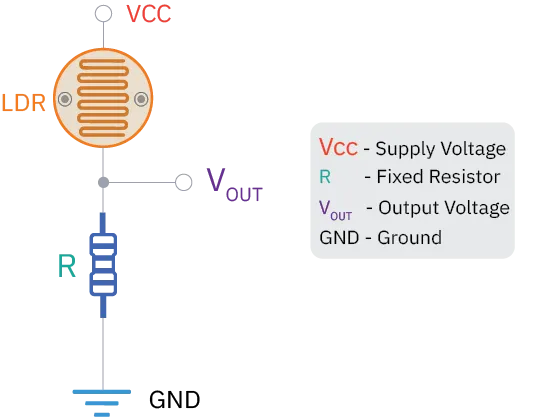
To achieve the voltage divider setup, one pin of the LDR is connected to Vcc (5V). The other pin of the LDR is connected in series to a resistor. The other end of the resistor is then connected to Ground (GND).
The output voltage (Vout) is taken from the point where the LDR and the resistor are connected.
Daytime Behavior
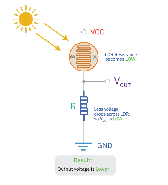
During the day there is more light, the LDR’s resistance becomes low, so the voltage at the output point becomes lower. This voltage is read by the UNDA.Xplora from the LDR pin connected to the resistor and converted into a low digital value, which is then used to control components like LEDs.
Nighttime Behavior
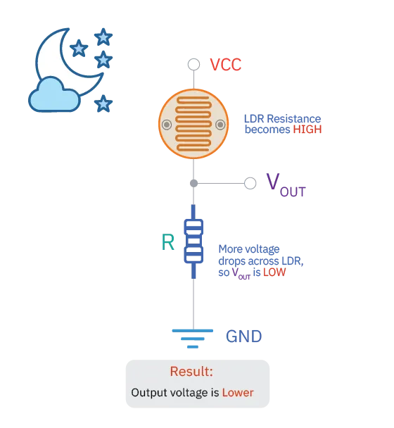
At night there is less light, the LDR’s resistance becomes high, so the voltage at the output point becomes higher. This voltage is read by the UNDA.Xplora from the LDR pin connected to the resistor and converted into a high digital value, which is then used to control components like LEDs.
Light vs. Resistance
The relationship between the illumination (Lux) and the resistance (R) of a Light Dependent Resistor (LDR) is inversely proportional. As the intensity of light falling on the sensor increases, the resistance decreases.
The Mathematical Relationship
This relationship is generally non-linear and follows a logarithmic curve. It is often expressed by the formula:
Light-Resistance Relationship
Where:
- R is the resistance of the LDR.
- L is the light intensity (Lux).
- A and γ are constants specific to the material used (usually Cadmium Sulfide).
The value of γ typically ranges between 0.6 and 0.9. On a log-log scale graph, this relationship appears as a straight line.
Typical Resistance Values
While every LDR model varies, a standard 5mm LDR usually follows these approximations:
| Lighting Condition | Light Level (Lux) | Typical Resistance |
|---|---|---|
Complete Darkness | 0.1 Lux |
|
Dim Room | 10 – 50 Lux | 10KΩ – 20KΩ |
Bright Office | 400 – 600 Lux | 1KΩ – 5KΩ |
Direct Sunlight | 10,000+ Lux | < 200Ω |
- Darkness: In the dark, the semi-conductive material has very few free electrons. This results in high resistance, blocking the flow of current.
- Light: When photons (light particles) hit the sensor, they provide energy to the electrons, knocking them loose.
- Conductivity: These free electrons allow current to flow more easily, causing the resistance to drop significantly.
Try it: LDR Simulation
Drag the slider from dark to sunlight to see everything update live.
Connecting the LDR
To connect the LDR on the breadboard follow these steps:
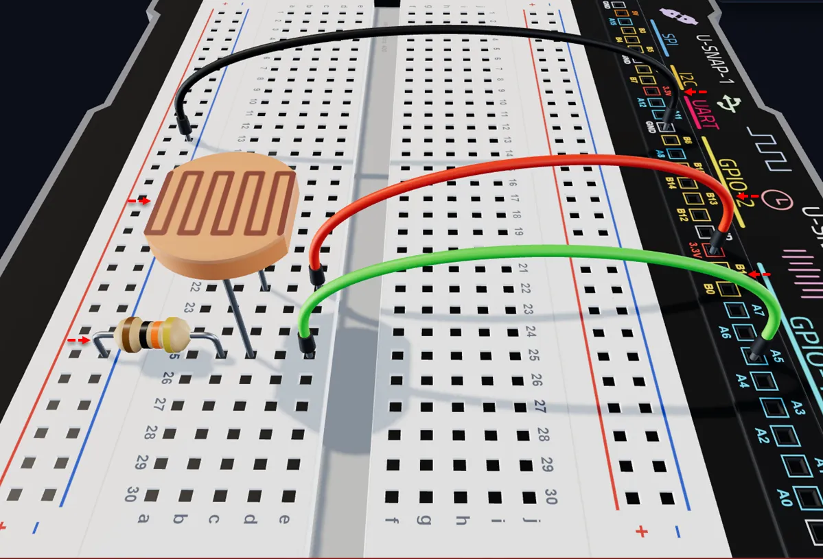
Place the LDR by inserting its two legs into the breadboard, e.g into pin c22 and c25.
Connect a 10 kΩ resistor from pin b25 (breadboard pin next to Pin 1) to any pin on the bottom negative breadboard rail.
Connect from the Pin 1 LDR to an ADC pin on the kit (e.g. A5) using a jumper wire.
Using a jumper wire, connect the other leg of the LDR (PIN 2) to the positive voltage supply, (3.3V or 5V).
Connect from GND Pin of the kit to the bottom negative breadboard rail using a jumper wire.
Common Issues and Fixes
When working with the LDR, some common issues that may prevent it from working include:
No Resistor Used – The circuit will not form a proper voltage divider, leading to incorrect readings.
Fix: Always connect a resistor in series with the LDR to create a voltage divider.Wrong Pin Used (Digital instead of Analog) – The system cannot read changing light levels correctly.
Fix: Connect the LDR output to an analog pin (e.g. A3).Loose or Incorrect Wiring – The sensor may give unstable or no readings.
Fix: Ensure all jumper wires are firmly and correctly connected.LDR Not Exposed to Light – The sensor will not respond properly if covered or placed wrongly.
Fix: Make sure the top surface of the LDR is exposed to light.Wrong Connection Setup – If not connected as a voltage divider, readings will not change properly.
Fix: Connect one leg to Vcc, the other to analog pin, and add a resistor to GND.
Practice Makes Perfect
Practice connecting the LDR and other components on the Xplora Virtual Simulator to better understand how circuits are built. This will help you gain confidence before working with real hardware and improve your wiring skills.
Conclusion
The LDR is a simple and useful light sensor that changes its resistance based on the amount of light it receives. When used in a voltage divider, it allows electronic systems to detect light levels and respond accordingly. This makes it ideal for projects such as automatic lighting, brightness control, and other smart applications that depend on light.
Build with the LDR
The projects listed below make use of the LDR.
Explore some fun Xplora projects that use the Light sensor (LDR) to see it in action: